


Implementing 3-Switch XOR Ladder Logic with Internal Bit
Implement a 3-SPST switch XOR light circuit in LogixPro or RSLogix 500 using an internal relay bit. Includes truth tables, boolean equations, and verified.

Executing core automation and sequential tasks in industrial environments, the Omron CP1E-N60SDR-A serves as an integrated, space-saving programmable controller designed for compact machinery. This application-ready unit integrates 36 digital inputs and 24 relay outputs directly onto its main chassis, eliminating the need for immediate expansion modules in standard configurations. Operating on a universal 100 to 240 VAC power supply, this controller manages complex logic with an 8k-step program capacity and an 8k-word data memory, making it a reliable solution for cost-sensitive automation tasks.
| Parameter | Specification Value |
|---|---|
| Manufacturer | Omron |
| Model Number | CP1E-N60SDR-A |
| Series | CP1E |
| Power Supply Voltage | 100 to 240 VAC, 50/60 Hz |
| Total Onboard I/O | 60 Points |
| Digital Inputs | 36 Inputs (24 VDC) |
| Digital Outputs | 24 Outputs (Relay) |
| Output Switching Type | Relay |
| Program Memory | 8k Steps |
| Data Memory | 8k Words |
| External Aux Power Supply | 24 VDC @ 0.30 A |
| Current Consumption (5 VDC) | 0.21 A |
| Current Consumption (24 VDC) | 0.13 A |
| Standards & Certifications | CE Compliant |
| Shipping Weight | 3 kg |
| Terminal Label | Functional Assignment |
|---|---|
| L1, L2/N | 100 to 240 VAC Primary Main Power Input |
| Protective Earth (PE) | Chassis Ground connection for noise immunity |
| + / - (Auxiliary) | 24 VDC output terminal for external sensor loop excitation |
| 00.00 to 02.11 | Direct 24 VDC Digital Inputs (Grouped Commons) |
| 10.00 to 12.07 | Normally-Open (NO) Relay Output Terminals |
| USB Port | Built-in peripheral port for standard programming via CX-Programmer |
The N-type (CP1E-N60SDR-A) features a built-in USB port and support for standard serial communication boards. If replacing a standard CP1E-E unit, confirm your configuration setup, as standard E-type logic programs that utilize specific instructions or serial interface add-ons will require system verification in CX-Programmer before execution.
When utilizing the built-in auxiliary 24 VDC power supply, avoid overloading past the 0.30 A limits. Running the auxiliary supply near its limits while operating under elevated ambient panel temperatures can trigger thermal shutdown mechanisms or lead to early component failure.
Ensure that inductive output loads, such as solenoids or contactor coils, have parallel suppression elements (freewheeling diodes for DC systems and RC snubbers for AC lines). Failing to suppress inductive kickback will wear out the onboard mechanical relay contacts prematurely and generate noise that can interrupt the PLC central processor.
Isolate and lock out all high-voltage electrical power sources feeding the system before mounting, wiring, or servicing the unit. Verify the total lack of voltage across input terminals. Failure to perform lock-out/tag-out procedures can cause severe electrical shock, physical injury, or total destruction of hardware components.
Mount the controller onto a standard 35 mm DIN rail in a horizontal orientation, allowing a minimum of 50 mm clearance above and below the device for natural air convection currents.
Connect the mains power line (100 to 240 VAC) directly to the designated AC power terminals using standard 1.25 mm square AWG wire, and tie the PE terminal directly to your central safety grounding point.
Route your input wiring (24 VDC logic) and high-voltage output wiring through separate, segregated wire trays to avoid electromagnetic induction noise on signal cables.
Global Express Shipping
Returns & Warranty

Manufacturer: Omron
Product No.: CP1E-N60SDR-A
Country of origin:Japan
Product Type: PLC CPU Modules
Payment: T/T, Western Union
Weight: 3000g
Shipping port: Xiamen
Warranty: 12 months
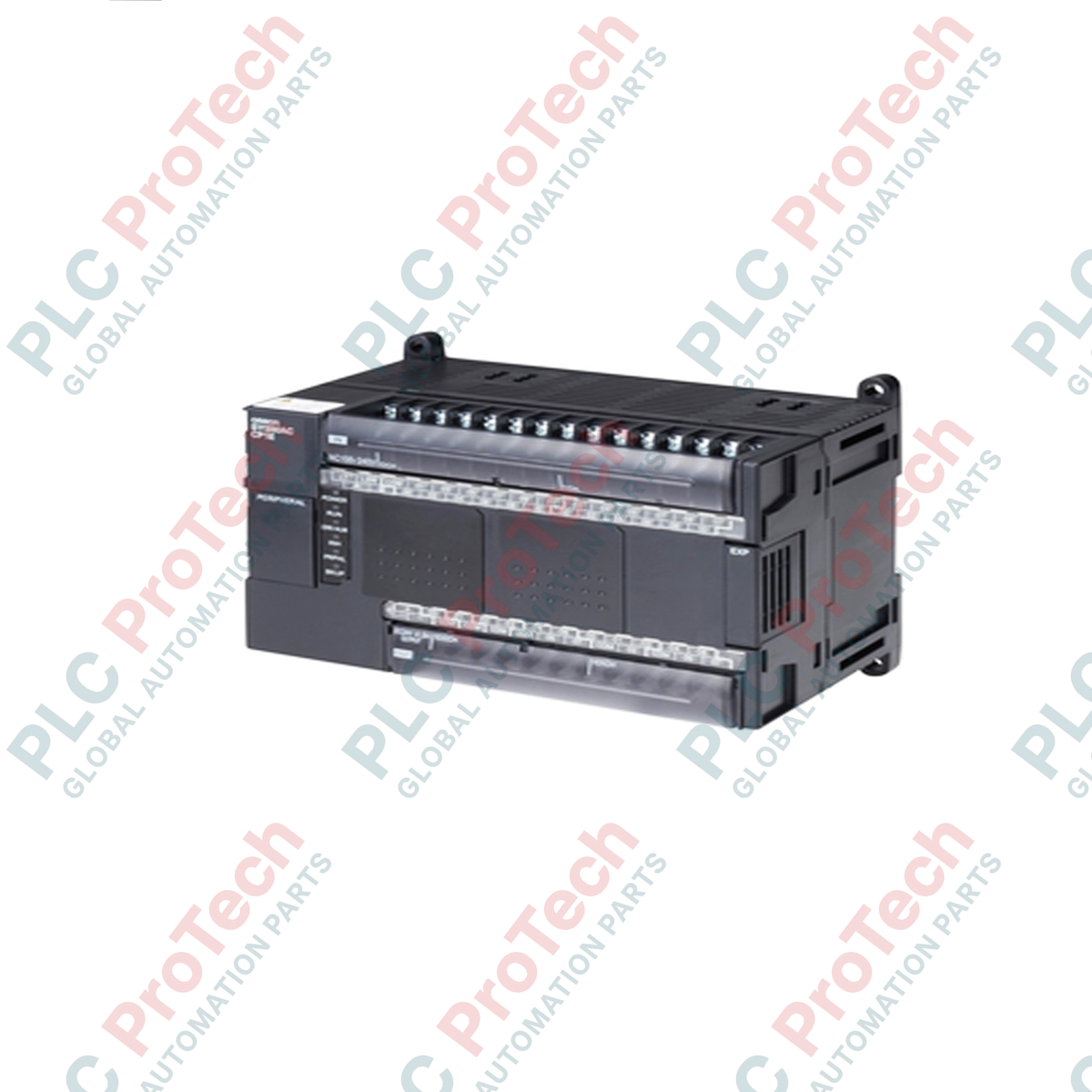
Executing core automation and sequential tasks in industrial environments, the Omron CP1E-N60SDR-A serves as an integrated, space-saving programmable controller designed for compact machinery. This application-ready unit integrates 36 digital inputs and 24 relay outputs directly onto its main chassis, eliminating the need for immediate expansion modules in standard configurations. Operating on a universal 100 to 240 VAC power supply, this controller manages complex logic with an 8k-step program capacity and an 8k-word data memory, making it a reliable solution for cost-sensitive automation tasks.
| Parameter | Specification Value |
|---|---|
| Manufacturer | Omron |
| Model Number | CP1E-N60SDR-A |
| Series | CP1E |
| Power Supply Voltage | 100 to 240 VAC, 50/60 Hz |
| Total Onboard I/O | 60 Points |
| Digital Inputs | 36 Inputs (24 VDC) |
| Digital Outputs | 24 Outputs (Relay) |
| Output Switching Type | Relay |
| Program Memory | 8k Steps |
| Data Memory | 8k Words |
| External Aux Power Supply | 24 VDC @ 0.30 A |
| Current Consumption (5 VDC) | 0.21 A |
| Current Consumption (24 VDC) | 0.13 A |
| Standards & Certifications | CE Compliant |
| Shipping Weight | 3 kg |
| Terminal Label | Functional Assignment |
|---|---|
| L1, L2/N | 100 to 240 VAC Primary Main Power Input |
| Protective Earth (PE) | Chassis Ground connection for noise immunity |
| + / - (Auxiliary) | 24 VDC output terminal for external sensor loop excitation |
| 00.00 to 02.11 | Direct 24 VDC Digital Inputs (Grouped Commons) |
| 10.00 to 12.07 | Normally-Open (NO) Relay Output Terminals |
| USB Port | Built-in peripheral port for standard programming via CX-Programmer |
The N-type (CP1E-N60SDR-A) features a built-in USB port and support for standard serial communication boards. If replacing a standard CP1E-E unit, confirm your configuration setup, as standard E-type logic programs that utilize specific instructions or serial interface add-ons will require system verification in CX-Programmer before execution.
When utilizing the built-in auxiliary 24 VDC power supply, avoid overloading past the 0.30 A limits. Running the auxiliary supply near its limits while operating under elevated ambient panel temperatures can trigger thermal shutdown mechanisms or lead to early component failure.
Ensure that inductive output loads, such as solenoids or contactor coils, have parallel suppression elements (freewheeling diodes for DC systems and RC snubbers for AC lines). Failing to suppress inductive kickback will wear out the onboard mechanical relay contacts prematurely and generate noise that can interrupt the PLC central processor.
Isolate and lock out all high-voltage electrical power sources feeding the system before mounting, wiring, or servicing the unit. Verify the total lack of voltage across input terminals. Failure to perform lock-out/tag-out procedures can cause severe electrical shock, physical injury, or total destruction of hardware components.
Mount the controller onto a standard 35 mm DIN rail in a horizontal orientation, allowing a minimum of 50 mm clearance above and below the device for natural air convection currents.
Connect the mains power line (100 to 240 VAC) directly to the designated AC power terminals using standard 1.25 mm square AWG wire, and tie the PE terminal directly to your central safety grounding point.
Route your input wiring (24 VDC logic) and high-voltage output wiring through separate, segregated wire trays to avoid electromagnetic induction noise on signal cables.
Global Express Shipping
Returns & Warranty
Orders are processed and delivered Monday-Friday (excluding public holidays).
For full eligibility, restocking fees, and international return details, please view our official Refund & Return Policy .
| Country of origin |
Japan
|

Implement a 3-SPST switch XOR light circuit in LogixPro or RSLogix 500 using an internal relay bit. Includes truth tables, boolean equations, and verified.

Integrate Allen-Bradley CompactLogix, Caterpillar ATS, and generators into DeltaV DCS over Modbus RTU. Covers ProSoft MVI69-MCM, Miille DIN266 gateways.

ONS instruction fires but the OTE coil never latches in Studio 5000 because the one-shot is only true for one scan. Use OTL/OTU or seal-in logic instead.

Configure Allen-Bradley Kinetix 5500 servo drives on EtherNet/IP. Covers CIP Sync, IEEE 1588 V2 timing, Stratix selection, DLR topology, and HMI.

A moving-average filter is the sliding-window smoother most instrument engineers drop into DCS and PLC analog paths. Here is how the window works, how N and sample time set lag, and when a...

On Frame 5–9 gas turbines, GE Mark VI and Mark VIe run control as function-block application software. This article maps process, protection, and sequencing functions—and what Toolbox ST access...