Description
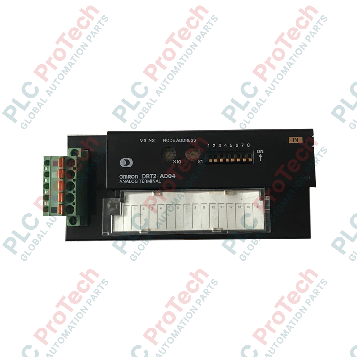
Distributed control environments requiring high-precision analog integration rely on the DRT2-AD04 analog input terminal to interface physical sensors with industrial networks. Operating as a DeviceNet smart slave, this module provides four distinct channels of configurable analog inputs, accommodating standard current loop and voltage signals to interface with Sysmac CJ/NJ Series automation platforms.
The module incorporates onboard diagnostic tools designed to simplify preventative maintenance. Users can monitor conversion status, detect sensor disconnection scenarios, and configure scaling and alarm thresholds directly via DeviceNet parameterization. Its localized smart features reduce the computational load on the host PLC by processing high-limit, low-limit, and peak-hold monitoring directly at the slave level.
Features
- Four independent analog input points supporting both voltage and current operating modes.
- Flexible analog signal selection: 0 to 5 V, 1 to 5 V, 0 to 10 V, -10 to 10 V, 0 to 20 mA, and 4 to 20 mA.
- Fast analog-to-digital conversion cycle configurable from 1 to 4 active channels, achieving a maximum conversion cycle of 4 ms for all 4 channels.
- High-precision 1/6,000 full-scale resolution ensuring accurate data rendering for sensitive industrial measurements.
- Convenient bus-powered operation, drawing a maximum of 90 mA from the DeviceNet communications power supply.
- Robust diagnostic suite providing sensor wire-break detection, value monitoring, and operational statistics tracking.
Applications
- Distributed process control utilizing pressure transmitters, flow sensors, and level indicators.
- Remote telemetry and signal aggregation in multi-zone manufacturing environments.
- Integration with CJ/NJ Series PLC networks for high-speed automated processing.
Technical Specifications
Parameter
Specification
| Manufacturer |
Omron |
| Model/Part Number |
DRT2-AD04 |
| Series |
DRT2 Smart Slaves |
| Analog Inputs |
4 points |
| Input Voltage Ranges |
0 to 5 V, 1 to 5 V, 0 to 10 V, -10 to 10 V |
| Input Current Ranges |
0 to 20 mA, 4 to 20 mA |
| AD Conversion Cycle |
4 ms max. (with 4 channels active; adjustable from 1 to 4 points) |
| AD Conversion Data (Unipolar) |
0000 to 1770 hex (for 0-5 V, 1-5 V, 0-10 V, 0-20 mA, 4-20 mA) |
| AD Conversion Data (Bipolar) |
F448 to 0BB8 hex (for -10 to 10 V) |
| Resolution |
1/6,000 (full scale) |
| Power Supply Source |
DeviceNet communications power supply |
| Current Consumption |
90 mA max. |
| Compatible Controllers |
CJ Series, NJ Series |
| Maximum Message Length |
542 bytes |
| Dimensions (H x W x D) |
5 cm x 4.97 cm x 11.5 cm |
| Weight |
0.2 kg |
Installation Guidelines
- Mount the terminal securely on standard 35 mm DIN rail in a clean, dry control panel enclosure.
- Always use shielded twisted-pair (STP) cabling for analog signals to minimize high-frequency electromagnetic interference.
- Ensure that the DeviceNet communications power supply is appropriately rated and stable before initializing network traffic.
- Isolate low-voltage signal wiring from high-voltage AC motor and power distribution cabling.