Description
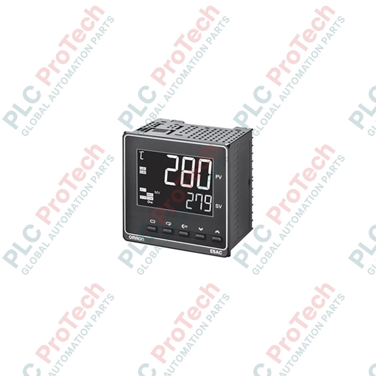
Managing thermal profiles with high precision, the Omron E5AC-RX2ASM-000 serves as a high-density, 1/4 DIN process controller engineered for demanding industrial environments. This unit integrates a high-contrast, white PV display with a fast 50 ms sampling rate to deliver rapid, reliable closed-loop control. Designed for standard panel-mount configurations, it accommodates universal sensor inputs and features dual relay outputs to handle primary control loops and critical process alarms without requiring auxiliary transmitter modules.
Features
-
High-Visibility White LCD Display: 25 mm high process value characters offer exceptional legibility from long distances and wide viewing angles.
-
Ultra-Fast Sampling Rate: 50 ms sampling period provides the response speed required for rapid temperature fluctuations in dynamic thermal processes.
-
Universal Sensor Input: Direct connection support for thermocouple, platinum resistance thermometer (Pt100/JPt100), and analog current/voltage signals.
-
Dual Auxiliary Relay Outputs: Two independent SPST-NO auxiliary outputs configurable for alarms, safety interlocks, or event states.
-
Compact Shallow Depth: A 60 mm depth behind the front panel minimizes spatial requirements inside space-constrained electrical cabinets.
Applications
- Plastic extrusion systems and injection molding equipment temperature zones.
- Industrial heat-treating furnaces, ovens, and ceramic kilns.
- High-speed packaging machinery sealing bars and hot-melt adhesive applicators.
- Environmental simulation chambers and biological incubation systems.
Technical Specifications
| Specification Parameter |
Technical Value |
| Manufacturer |
Omron |
| Model / SKU |
E5AC-RX2ASM-000 |
| Front Panel Size |
96 x 96 mm (1/4 DIN) |
| Supply Voltage |
100 to 240 VAC, 50/60 Hz |
| Power Consumption |
9.0 VA max. |
| Control Output 1 |
Relay output (SPST-NO, 250 VAC, 3 A resistive load) |
| Control Output 2 |
None |
| Auxiliary Outputs |
2 SPST-NO relays (250 VAC, 2 A resistive load) |
| Input Sensor Compatibility |
Thermocouple (K, J, T, E, L, U, N, R, S, B, W, PL II), RTD (Pt100, JPt100), Analog (4-20 mA, 0-20 mA, 1-5 V, 0-5 V, 0-10 V) |
| Sampling Period |
50 ms |
| Control Method |
ON/OFF control or 2-PID control (with auto-tuning) |
| Terminal Connection |
Screw terminal block (M3) with integrated terminal cover |
| Operating Temperature |
-10 to 55 degC (no icing or condensation) |
| Country of Origin |
Japan |
| Shipping Weight (Calculated) |
0.45 kg |
| Package Dimensions (Calculated) |
120 mm x 120 mm x 110 mm |
Terminal Map and Interface Assignments
| Terminal Number |
Functional Circuit Assignment |
| 1 & 2 |
Operating Power Supply Input (100 to 240 VAC, non-polarized) |
| 3 & 4 |
Control Output 1 (Relay, SPST-NO) |
| 7 & 8 |
Auxiliary Output 1 (Relay, SPST-NO) |
| 9 & 10 |
Auxiliary Output 2 (Relay, SPST-NO) |
| 21, 22, 23 |
Universal Sensor Input (RTD Phase A/B/B' or TC / Voltage / Current) |
Empirical Engineering Insights
Alternative Models & Compatibility
The E5AC-RX2ASM-000 is a direct 1/4 DIN successor to legacy E5AN models. Unlike older iterations, this unit features a drastically reduced panel-mount depth of 60 mm, allowing installation in shallow enclosures. Note that while its parameter structure is highly aligned with legacy platforms, register map shifts may require verification if adapting existing Modbus communication loops via external gateways.
Application Pitfalls & Engineering Notes
When utilizing the integrated 50 ms fast sampling mode, high-frequency electromagnetic fields from surrounding variable frequency drives (VFDs) can cause sensor value jitter or premature sensor-break errors (S.ERR). To prevent unstable process feedback, the input digital filter parameter (dFL) should be incrementally increased from the default 0.0 seconds to approximately 1.0 or 2.0 seconds in electrically noisy environments.
Commissioning & Wiring Tips
For initial thermal commissioning, configure the controller’s auto-tuning (AT) command only after the system has stabilized at room temperature. Executing auto-tuning from a hot state may cause the controller to calculate inaccurate PID gains, leading to cyclic overshoot. If wiring thermocouple inputs, always use the matching alloy-compensated extension wire directly to terminals 21 and 22 to prevent secondary cold-junction errors.
Installation Guidelines
CRITICAL WARNING: De-energize all primary and auxiliary power lines before commencing installation or terminal wiring. Do not touch terminal screws 1 and 2 while mains power is active. Failure to strictly follow electrical isolation protocols can result in severe shock hazard, equipment destruction, or unexpected process startup.
1
Insert the E5AC process controller directly through the standard 92 mm x 92 mm panel cutout from the front of the electrical panel.
2
Slide the two mounting adapters over the top and bottom of the unit casing from behind the panel until they click firmly into place against the inner panel face.
3
Wire the input sensor using shielded pair cables to terminals 21-23, ensuring shield drain wire is properly grounded only at the system's single star-ground point.
4
Secure the power supply (100 to 240 VAC) to terminals 1 and 2, verify connection tightness to a torque of 0.43 to 0.58 N-m, and snap on the safety terminal cover.