Technical Overview
The E5AN-Q3MT-500-N is an advanced 1/4 DIN industrial digital temperature controller designed for high-precision thermal process regulation. In mission-critical industrial applications such as semiconductor manufacturing, plastics extrusion, metallurgical heat treatment, and glass annealing, strict thermal stabilization is paramount to preventing structural defects and minimizing operational downtime. This controller utilizes an advanced 2-PID control algorithm with auto-tuning to achieve optimal thermal trajectories while suppressing overshoot. Equipped with a high-speed sampling loop of 60 milliseconds and high-resolution multi-inputs, the instrument ensures deterministic process control under highly dynamic thermal load variations.
Control Architecture & System Configuration
The controller is engineered with a modular hardware configuration tailored for high-reliability process loops. It features a universal input stage that natively supports various thermocouple types (K, J, T, E, L, U, N, R, S, B, W, PL II), platinum resistance thermometers (Pt100, JPt100), and analog voltage/current inputs (4-20 mA, 0-20 mA, 1-5 V, 0-5 V, 0-10 V). The control output block is configured with a voltage output (12 VDC) optimized for driving external Solid State Relays (SSRs) in high-cycling proportional control applications. To enhance localized safety interlocks, the architecture includes three independent auxiliary relay outputs for flexible alarm signaling. The "-500" suffix designates the inclusion of a terminal cover as a standard safety accessory, protecting field technicians from high-voltage terminal paths.
Equipment Specifications
| Parameter |
Specification Details |
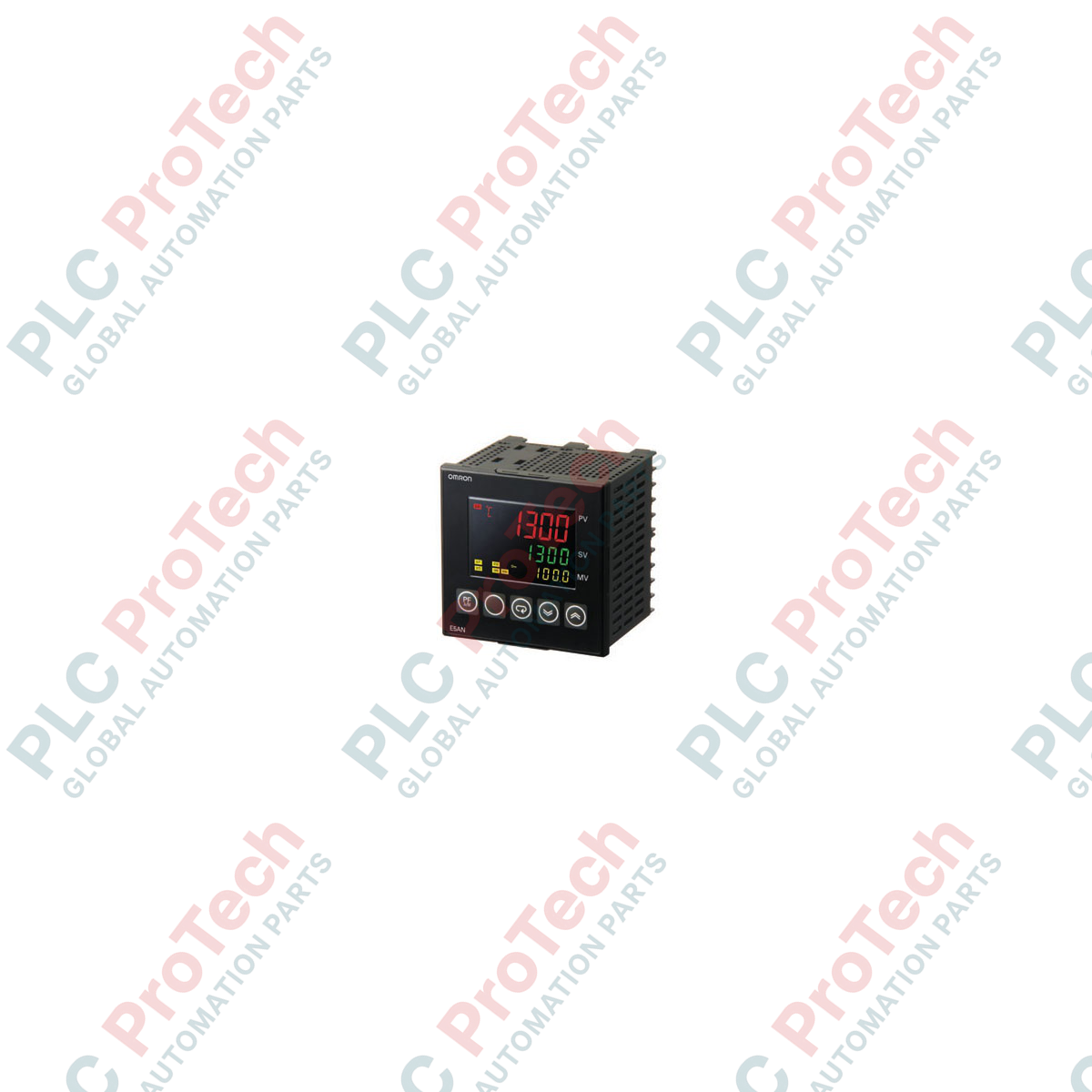
| Model |
E5AN-Q3MT-500-N |
| Brand |
OMRON |
| Origin |
Japan |
| Controller Size |
1/4 DIN (96 mm x 96 mm x 78 mm) |
| Input Type |
Universal Input (Thermocouple, Platinum RTD, Analog V/mA) |
| Control Output |
Voltage Output for driving SSR (12 VDC, PNP, maximum 21 mA) |
| Auxiliary Outputs |
3 Relay Outputs (SPST-NO, 250 VAC, 3 A resistive load) |
| Sampling Period |
60 ms |
| Supply Voltage |
100 to 240 VAC, 50/60 Hz |
| Power Consumption |
10 VA maximum |
| Indication Method |
11-Segment Digital Display (PV: 15.8 mm, SV: 9.5 mm) |
| Terminal Type |
M3 Screw Terminals |
| Weight |
0.31 kg |
| Operating Temperature |
-10 to 55 deg C (with no icing or condensation) |
Hardware FAQs
What is the functional difference between the older E5AN-Q3MT-500 and the "-N" version?
The "-N" designation indicates OMRON's upgraded series generation. It features an enhanced 60 ms sampling cycle (down from 250 ms), an upgraded 11-segment high-visibility display panel, and expanded advanced tuning parameters. It serves as a direct downward-compatible replacement for the legacy non-N models.
Can the auxiliary relay outputs on this unit be configured as control outputs?
No. The primary loop regulation must be handled by the 12 VDC voltage output driving an SSR. The three auxiliary outputs are strictly software-mapped internal relays reserved for event alarms (e.g., upper/lower limits, deviation, loop burnout) or basic logical interlocks.
Does this model require manual hardware jumpers to change from a K-type thermocouple to a Pt100 RTD sensor?
No hardware jumper changes are required. The input stage is fully universal. Field technicians simply modify the internal software parameter configuration via the front display panel or CX-Thermo software to change the sensor characteristics.
Field Installation & Wiring Directives
-
Enclosure Cutout and Mounting: Prepare a standard 1/4 DIN square panel cutout measuring 92 mm x 92 mm. Insert the controller through the panel front and secure it tightly from the rear using the provided mounting brackets. Tighten the fixing screws to a torque of 0.43 to 0.58 N-m to ensure a tight NEMA 4X/IP66 front panel seal.
-
Sensor Shielding and Input Separation: To minimize high-frequency noise corruption on low-voltage thermocouple or RTD inputs, run sensor cables through dedicated grounded metal conduits. Ensure input lines are separated from heavy 230/400 VAC power supply switches and motor line feeds by at least 200 mm.
-
Proportional Control SSR Wiring: Connect the 12 VDC voltage control output directly to the input terminals of the external Solid State Relay (SSR). Observe correct polarity (Terminal 1 positive, Terminal 2 negative). Ensure the combined loop current does not exceed 21 mA to avoid internal transistor damage.
-
Thermal and Environment Management: Avoid installing the unit in environments with high concentrations of corrosive gases (such as sulfur or ammonia). When mounting multiple controllers horizontally in a single panel matrix, maintain a minimum clearance of 20 mm between units and ensure internal panel ambient temperatures remain below 55 deg C.