Description
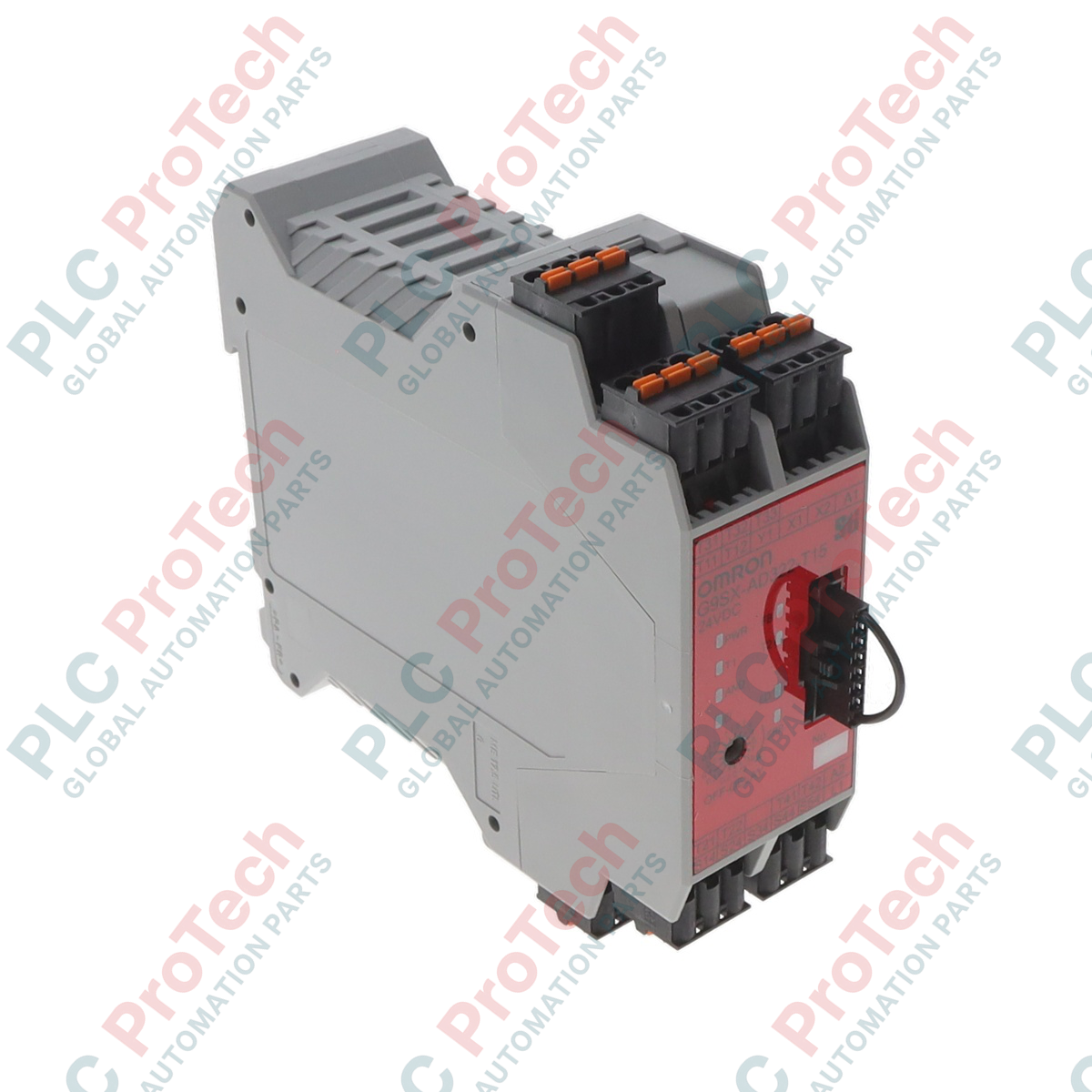
Facilitating safe system expansion and precise timing control across complex machine layouts, the Omron G9SX-AD322-T150-RC flexible safety unit delivers advanced safety logic integration without complex programming. This advanced safety controller features solid-state safety outputs configured for both instantaneous shut-off and controlled deceleration profiles. Built with a spring-cage terminal interface, the hardware ensures gas-tight, vibration-proof electrical terminations ideal for high-stress manufacturing environments.
Features
- Configurable OFF-delay times up to 150 seconds via synchronized front-panel rotary dials.
- Three instantaneous solid-state safety outputs and two OFF-delayed safety outputs for staged system shutdowns.
- Spring-cage (tension clamp) terminal blocks for rapid installation and long-term connection reliability.
- Two auxiliary outputs providing clear diagnostics and machine status communication directly to control PLCs.
- Logical AND connection capability to cascade multiple safety units while preserving safety integrity levels.
Applications
- Robotic work cell safety integration requiring delayed interlocking guard access until complete arm deceleration.
- Emergency stop circuits necessitating controlled motor ramp-down prior to physical brake application.
- Complex packaging line synchronization requiring zoned safety shutdown capabilities.
- Safety light curtain integration paired with automated process gates.
Technical Specifications
| Manufacturer |
Omron |
| Model Reference |
G9SX-AD322-T150-RC |
| Unit Classification |
Advanced Safety Unit |
| Rated Supply Voltage |
24 VDC |
| Operating Voltage Range |
20.4 to 26.4 VDC (-15% to +10% of nominal) |
| Power Consumption |
4.0 W maximum |
| Instantaneous Safety Outputs |
3 Semiconductor (P-channel MOS FET) |
| OFF-delayed Safety Outputs |
2 Semiconductor (P-channel MOS FET) |
| Auxiliary Outputs |
2 PNP Transistor (100 mA maximum) |
| Max. OFF-delay Configuration |
150 seconds |
| Load Current (1 to 2 active outputs) |
1.0 A DC maximum per output |
| Load Current (3 or more active outputs) |
0.8 A DC maximum per output |
| Safety Input Impedance |
Approximately 2.8 kOhms |
| Connection Style |
Spring-cage terminals (RC model) |
| Vibration Resistance |
10 to 55 to 10 Hz, 0.375 mm single amplitude |
| Net Unit Weight |
0.2 kg |
| Shipping Weight |
1.5 kg |
Connections and Interfaces
| Terminal Block Designation |
Functional Circuit Assignment |
| A1, A2 |
Power supply connections (24 VDC and 0 VDC reference) |
| T11, T12 / T21, T22 |
Dual-channel safety sensor/switch inputs |
| T31, T32 |
Feedback loop and manual reset inputs |
| S14, S24, S34 |
Instantaneous safety semiconductor outputs |
| S44, S54 |
OFF-delayed safety semiconductor outputs |
| Y1, Y2 |
Auxiliary solid-state outputs for diagnostic communication |
Empirical Engineering Insights
Alternative Models & Compatibility
The G9SX-AD322-T150-RC features spring-cage terminals, which represent the direct structural and electrical alternative to the G9SX-AD322-T150-RT model (which utilizes traditional screw terminals). Because both variants share an identical internal logic engine and mounting footprint, they are completely interchangeable from a system engineering standpoint. However, the terminal plugs themselves cannot be directly cross-connected due to physical housing differences; wiring must be re-terminated with ferrules for optimal performance in the RC unit.
Application Pitfalls & Engineering Notes
When configuring the OFF-delay timing on the G9SX-AD322-T150-RC, engineers must adjust both rotational switches on the front panel to the exact same delay coefficient. If the two dials do not match precisely, the unit detects an asymmetrical layout parameter and enters a lock-out fault status, disabling all safety outputs. To reset this fault condition, set both dials to identical configurations and cycle the main 24 VDC supply voltage.
Commissioning & Wiring Tips
For optimal termination reliability, utilize insulated wire ferrules with a crimp length of 10 mm. Avoid using bare stranded copper wire in the spring-cage terminals, as single stray strands can cause local resistance faults or physical short-circuits. Utilize a 2.5 mm flat-head screwdriver inside the actuation slot to open the internal tension clamp during termination or diagnostic procedures.
Installation Guidelines
CRITICAL WARNING: Prior to attempting installation, configuration, or physical wiring adjustments on the safety unit, isolate and lock out all upstream electrical power sources. Verify the absence of residual voltage across all power and output lines before proceeding to avoid severe electrical hazards.
-
1
DIN-Rail Mounting: Snap the safety unit securely onto standard 35 mm DIN rail inside a protective electrical enclosure rated for the application environment (minimum IP54 rating recommended).
-
2
Terminal Block Connection: Insert the designated ferruled wire leads into the spring-cage terminals by depressing the adjacent actuation slot using a dedicated 2.5 mm flat tool.
-
3
Time-Delay Calibration: Configure the integrated rotary switches to align with the desired machine deceleration delay profile, ensuring both front-panel dials are dialed to the identical numeric value.
-
4
Functional System Test: Energize the module, verify the green LED diagnostic indications, and execute a controlled system verification test to confirm active-low safety response profiles.