Description
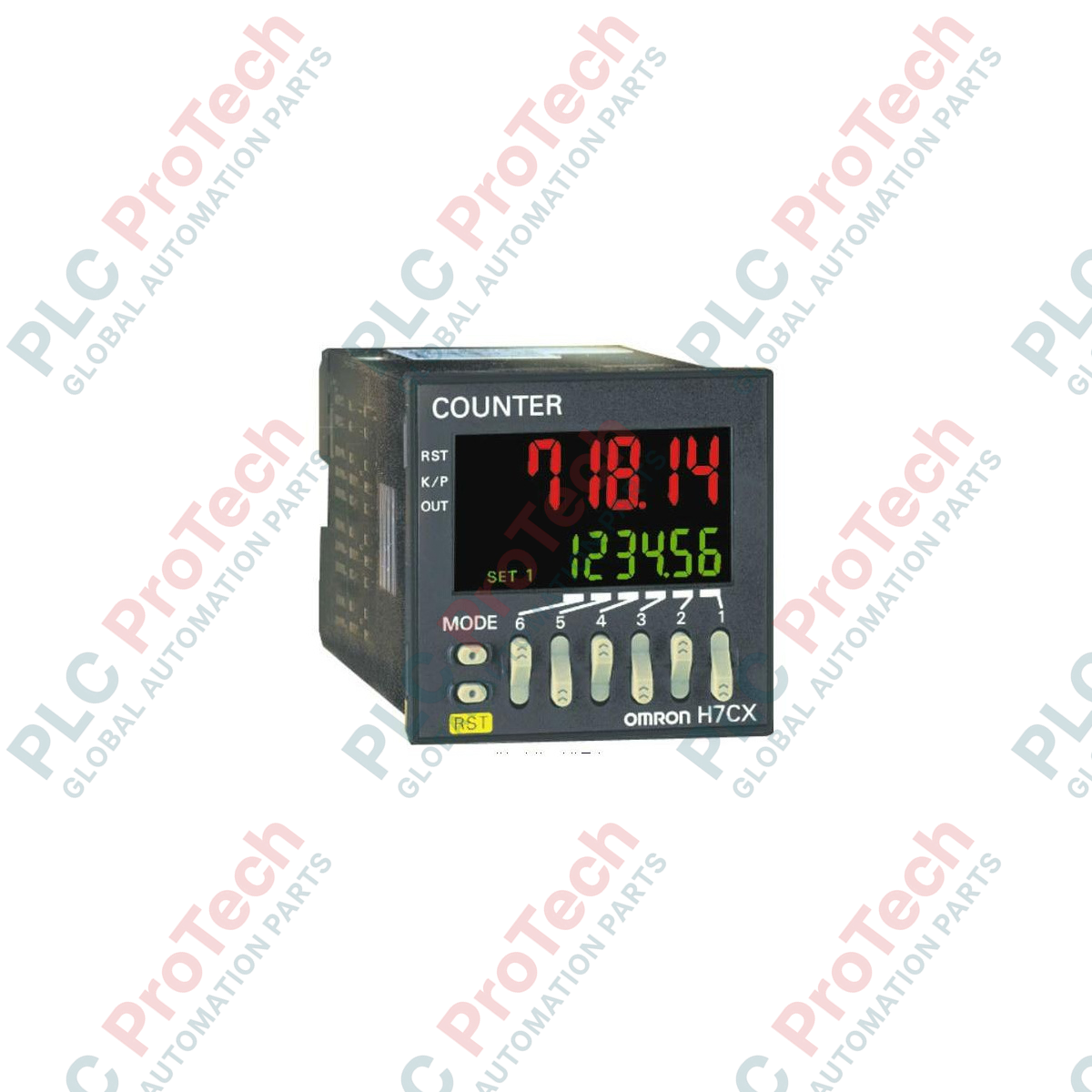
Integrated seamlessly into modern processing lines, the Omron H7CX-A11D1-N functions as a high-precision 1/16 DIN digital counter and tachometer engineered for rapid pulse monitoring and output coordination. Equipped with a vivid, dual-color PV character display, this multi-mode controller enables operations personnel to track counts, batches, and velocity metrics on a single, compact panel footprint. The device supports a multi-voltage control bus and integrates flexible contact and solid-state output paths to drive secondary automation processes safely and reliably.
Key Features
-
6-Digit PV Display: High-visibility red/green configurable characters for real-time process monitoring.
-
Flexible Multi-Mode Operation: Configurable as a 1-stage counter, batch counter, totalizing counter, dual counter, or digital tachometer.
-
11-Pin Socket Interface: Enables rapid electrical connection, physical swap-out, and robust integration.
-
Hybrid Output Configurations: Provides simultaneous availability of physical contact (SPDT) and solid-state transistor (NPN/PNP) outputs.
-
Universal Low-Voltage Power: Compatible with both 12 to 24 VDC and 24 VAC power distribution grids.
Industrial Applications
- High-speed packaging, sorting, and volumetric carton counting.
- Rotational machinery velocity and continuous line-speed tachometry monitoring.
- Batch-process cycle counting and material-cut control systems.
- Positioning and dimensional measurements using quadrature pulse inputs.
Technical Specifications
| Specification Parameter |
Engineering Value |
| Manufacturer |
Omron |
| Model Reference |
H7CX-A11D1-N |
| Display Digits |
6 digits (-99999 to 999999) |
| Power Supply Voltage |
12 to 24 VDC / 24 VAC at 50/60 Hz |
| External Connections |
11-pin socket connection layout |
| Input Processing Speed |
30 Hz or 5 kHz (DIP-switch selectable) |
| Output Types |
Contact (SPDT: 250 VAC, 3 A resistive) and Transistor (NPN/PNP open collector: 30 VDC, 100 mA) |
| Key Protection Range |
Physical lockout via internal firmware levels |
| Operating Temperature Limit |
-10 to 55 degC (with no icing or condensation) |
| Front Bezel Rating |
IP66 / NEMA 4X (dust-proof and drip-proof) |
| Shipping Weight (Calculated) |
2.0 kg (including safe protective box layers) |
| Bezel Dimensions (Calculated) |
48.0 mm x 48.0 mm (1/16 DIN panel mount style) |
| Body Insertion Depth |
84.1 mm |
Connections and Interfaces
| 11-Pin Terminal |
Function Assignment |
| Pin 1 |
Input Common (GND) |
| Pin 2 |
Power Supply Input (12-24 VDC / 24 VAC) |
| Pin 3 |
Count Input 1 (CP1 Signal Input) |
| Pin 4 |
Count Input 2 (CP2 Signal Input) |
| Pin 5 |
Reset Input / Gateway Command Signal |
| Pin 6 |
Transistor Output Emitter / Common |
| Pin 7 |
Power Supply Input (12-24 VDC / 24 VAC) |
| Pin 8 |
Transistor Output Collector (NPN/PNP Option) |
| Pin 9 |
Contact Output Relay Common (COM) |
| Pin 10 |
Contact Output Relay Normally Closed (NC) |
| Pin 11 |
Contact Output Relay Normally Open (NO) |
Empirical Engineering Insights
Alternative Models & Compatibility
The -N suffix variants directly replace legacy H7CX 11-pin models. While pin assignments remain strictly identical, note that default internal program parameters may vary between standard and newer revisions. Verify DIP switch configuration on the side housing to ensure that internal division ratios, counting modes, and response profiles align with the historical installation configuration.
Application Pitfalls & Engineering Notes
When configuring for the maximum 5 kHz count speed, ensure input signals originate from solid-state, non-contact proximity sensors or rotary encoders. Mechanical contact inputs will suffer from physical contact bounce, resulting in erratic, false-high counts. If a mechanical switch interface must be used, lower the maximum input counting speed to 30 Hz via the physical DIP switches to activate the internal low-pass noise filter.
Commissioning & Wiring Tips
Ensure that all high-voltage cabling (specifically output contacts switching heavy inductive loads) is routed in physical separation from input sensor paths. Use twisted-pair shielded cabling for CP1, CP2, and Reset inputs, grounding the shield exclusively at the panel terminal block to mitigate electromagnetically induced signal noise from surrounding active drives and switchgear.
Installation Guidelines
CRITICAL WARNING: Prior to attempting physical installation, wiring, or maintenance procedures, ensure all primary, auxiliary, and power supply lines feeding the panel environment are completely de-energized. Confirm that no residual charge resides on secondary capacitor banks or sensor lines to avoid potential equipment failure or physical shock hazards.
1
Prepare a standard 45.0 mm x 45.0 mm panel cutout matching standard DIN specifications.
2
Affix the waterproof gasket around the front housing shoulder to achieve NEMA 4X / IP66 front-face protection.
3
Slide the module from the front into the panel cutout, then slide the mounting adapter bracket onto the chassis from the rear, tightening physical panel screws until hand-tight.
4
Configure the physical DIP switch bank located on the rear or side panel according to the required function, input logic (NPN vs PNP), and sensor speed requirements.
5
Verify connection loops against the 11-pin socket pin configuration map, secure the socket onto the unit, and apply power lines to initiate commissioning.