


Implementing 3-Switch XOR Ladder Logic with Internal Bit
Implement a 3-SPST switch XOR light circuit in LogixPro or RSLogix 500 using an internal relay bit. Includes truth tables, boolean equations, and verified.

Rotary position monitoring and control are managed efficiently by the Omron H8PS-8BP, an 8-channel electronic cam positioner engineered to replace traditional mechanical cam systems in high-speed industrial machinery. This compact 1/4 DIN panel-mounted instrument processes raw encoder signals to execute precise, angle-based switching. Featuring a clear, backlit LCD screen, the Omron H8PS-8BP provides real-time position feedback and status indications directly on the plant floor. Configured with 8 PNP transistor outputs, it delivers fast response times and seamless integration with industrial PLC systems and monitoring hardware.
| Parameter | Specification |
|---|---|
| Manufacturer | Omron |
| Model Number | H8PS-8BP |
| Device Type | Cam Positioner |
| Output Type | PNP Transistor |
| Number of Outputs | 8 |
| Input Signal Type | Encoder (Dedicated Omron Absolute Encoder) |
| Supply Voltage Range | 20.4 to 26.4 VDC |
| Display Type | 7-segment LCD with backlight |
| Front Panel Dimensions | 96 mm x 96 mm (1/4 DIN) |
| Mounting Depth | 67.5 mm |
| Net Product Weight | 300 g |
| Shipping Weight (Calculated) | 1.5 kg |
| Country of Origin | Japan |
The rear of the instrument features dedicated hardware DIP switches allowing the system integrator to define operational characteristics before system startup. Use these switches to toggle the encoder's direction logic between clockwise (CW) and counterclockwise (CCW) rotation without rebuilding internal wiring or modifying downstream PLC code.
Ensure compatibility with your active encoder model. The H8PS-8BP is designed to pair natively with specified Omron absolute encoders (such as the E6C3-A series). Using incremental or non-supported absolute encoders will result in signal processing errors on startup.
When switching inductive loads directly with the PNP transistor outputs, installation of external surge-suppression diodes is highly recommended. Transient voltage spikes from unsuppressed inductive loads can lead to thermal degradation of the internal output transistors over extended operational cycles.
Always route the encoder signal cable through a dedicated, grounded metallic conduit separate from high-voltage AC power lines. Parallel runs alongside variable frequency drive (VFD) output cables can introduce electromagnetic noise, causing intermittent angular reading fluctuations on the LCD display.
Isolate and verify the de-energization of all power sources prior to starting installation or wiring. Do not hot-plug the encoder or output connector terminal blocks to prevent permanent semiconductor damage from capacitive discharge.
Prepare a clean 92 x 92 mm panel cutout according to standard 1/4 DIN tolerances.
Insert the H8PS-8BP through the cutout from the front, ensuring the protective rubber gasket is seated properly to preserve panel seal integrity.
Slide the mounting brackets into the side channels on the housing and tighten the retention screws evenly.
Set the encoder direction DIP switch on the rear panel according to your physical installation orientation (CW or CCW).
Terminate the absolute encoder connections, the 8 PNP output circuits, and the 24 VDC auxiliary power line to the secure rear terminal block.
Global Express Shipping
Returns & Warranty

Manufacturer: Omron
Product No.: H8PS-8BP
Country of origin:Japan
Product Type: Cam Positioners
Payment: T/T, Western Union
Weight: 500g
Shipping port: Xiamen
Warranty: 12 months
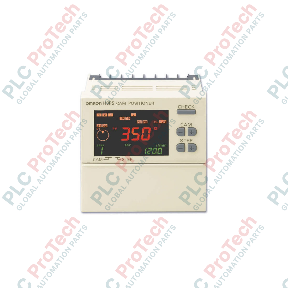
Rotary position monitoring and control are managed efficiently by the Omron H8PS-8BP, an 8-channel electronic cam positioner engineered to replace traditional mechanical cam systems in high-speed industrial machinery. This compact 1/4 DIN panel-mounted instrument processes raw encoder signals to execute precise, angle-based switching. Featuring a clear, backlit LCD screen, the Omron H8PS-8BP provides real-time position feedback and status indications directly on the plant floor. Configured with 8 PNP transistor outputs, it delivers fast response times and seamless integration with industrial PLC systems and monitoring hardware.
| Parameter | Specification |
|---|---|
| Manufacturer | Omron |
| Model Number | H8PS-8BP |
| Device Type | Cam Positioner |
| Output Type | PNP Transistor |
| Number of Outputs | 8 |
| Input Signal Type | Encoder (Dedicated Omron Absolute Encoder) |
| Supply Voltage Range | 20.4 to 26.4 VDC |
| Display Type | 7-segment LCD with backlight |
| Front Panel Dimensions | 96 mm x 96 mm (1/4 DIN) |
| Mounting Depth | 67.5 mm |
| Net Product Weight | 300 g |
| Shipping Weight (Calculated) | 1.5 kg |
| Country of Origin | Japan |
The rear of the instrument features dedicated hardware DIP switches allowing the system integrator to define operational characteristics before system startup. Use these switches to toggle the encoder's direction logic between clockwise (CW) and counterclockwise (CCW) rotation without rebuilding internal wiring or modifying downstream PLC code.
Ensure compatibility with your active encoder model. The H8PS-8BP is designed to pair natively with specified Omron absolute encoders (such as the E6C3-A series). Using incremental or non-supported absolute encoders will result in signal processing errors on startup.
When switching inductive loads directly with the PNP transistor outputs, installation of external surge-suppression diodes is highly recommended. Transient voltage spikes from unsuppressed inductive loads can lead to thermal degradation of the internal output transistors over extended operational cycles.
Always route the encoder signal cable through a dedicated, grounded metallic conduit separate from high-voltage AC power lines. Parallel runs alongside variable frequency drive (VFD) output cables can introduce electromagnetic noise, causing intermittent angular reading fluctuations on the LCD display.
Isolate and verify the de-energization of all power sources prior to starting installation or wiring. Do not hot-plug the encoder or output connector terminal blocks to prevent permanent semiconductor damage from capacitive discharge.
Prepare a clean 92 x 92 mm panel cutout according to standard 1/4 DIN tolerances.
Insert the H8PS-8BP through the cutout from the front, ensuring the protective rubber gasket is seated properly to preserve panel seal integrity.
Slide the mounting brackets into the side channels on the housing and tighten the retention screws evenly.
Set the encoder direction DIP switch on the rear panel according to your physical installation orientation (CW or CCW).
Terminate the absolute encoder connections, the 8 PNP output circuits, and the 24 VDC auxiliary power line to the secure rear terminal block.
Global Express Shipping
Returns & Warranty
Orders are processed and delivered Monday-Friday (excluding public holidays).
For full eligibility, restocking fees, and international return details, please view our official Refund & Return Policy .
| Country of origin |
Japan
|

Implement a 3-SPST switch XOR light circuit in LogixPro or RSLogix 500 using an internal relay bit. Includes truth tables, boolean equations, and verified.

Integrate Allen-Bradley CompactLogix, Caterpillar ATS, and generators into DeltaV DCS over Modbus RTU. Covers ProSoft MVI69-MCM, Miille DIN266 gateways.

ONS instruction fires but the OTE coil never latches in Studio 5000 because the one-shot is only true for one scan. Use OTL/OTU or seal-in logic instead.

Configure Allen-Bradley Kinetix 5500 servo drives on EtherNet/IP. Covers CIP Sync, IEEE 1588 V2 timing, Stratix selection, DLR topology, and HMI.

A moving-average filter is the sliding-window smoother most instrument engineers drop into DCS and PLC analog paths. Here is how the window works, how N and sample time set lag, and when a...

On Frame 5–9 gas turbines, GE Mark VI and Mark VIe run control as function-block application software. This article maps process, protection, and sequencing functions—and what Toolbox ST access...