Description
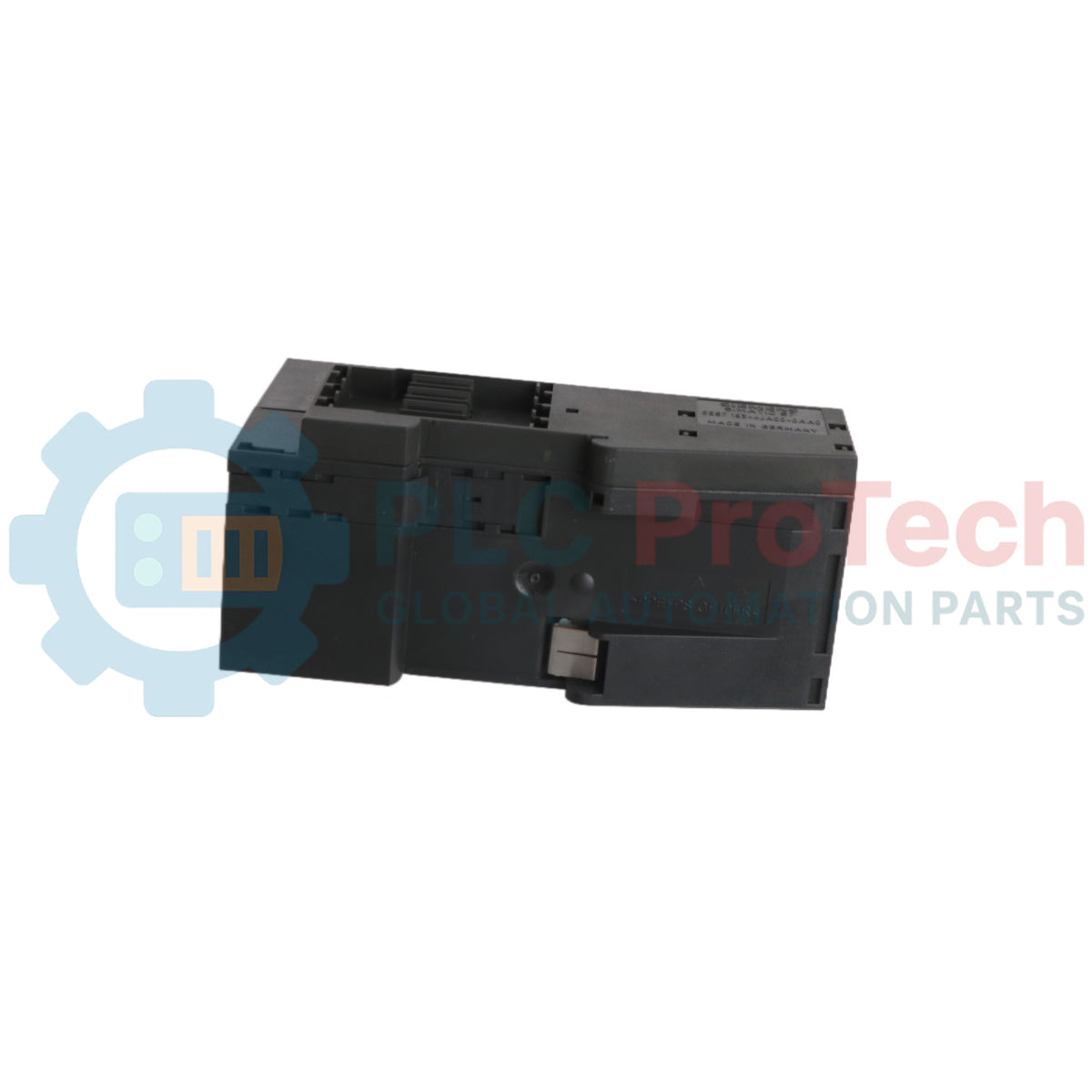
This is a Siemens 6ES7151-1AA06-0AB0 interface module for the SIMATIC ET 200S distributed I/O system. It functions as the head station, managing communication between a higher-level controller and the connected I/O modules via PROFIBUS DP. The module supports both PROFIBUS DP V0 and V1 protocols and can manage an extensive system of up to 63 I/O modules. It is designed to handle a data volume of 244 bytes for inputs and 244 bytes for outputs, ensuring efficient data exchange for control and monitoring tasks. The module operates on a standard 24 V DC supply and includes a termination module for proper bus installation.
Features
-
■Supports PROFIBUS DP V0 and V1 protocols for flexible network integration.
-
■Manages up to 63 peripheral I/O modules.
-
■Data volume capacity of 244 bytes for inputs and 244 bytes for outputs.
-
■Operates on a nominal 24 V DC power supply.
-
■Connects to the PROFIBUS network via a standard 9-pin D-sub connector.
-
■Allows for a maximum station width of up to 2 meters.
Applications
-
■Discrete manufacturing and assembly lines.
-
■Process control systems in chemical and pharmaceutical plants.
-
■Machinery automation and OEM equipment.
-
■Material handling and conveyor systems.
Technical Specifications
| Specification |
Value |
| Manufacturer |
Siemens |
| Model Number |
6ES7151-1AA06-0AB0 |
| Product Series |
SIMATIC ET 200S |
| Module Type |
Interface Module (IM 151-1 Standard) |
| Communication Protocol |
PROFIBUS DP V0, V1 |
| Bus Connection |
9-pin D-sub Connector |
| Supply Voltage |
24 V DC |
| Input Current (from supply) |
200 mA |
| Output Capacity |
80 mA |
| Max. Number of I/O Modules |
63 |
| Data Volume (Inputs) |
244 bytes |
| Data Volume (Outputs) |
244 bytes |
| Max. Station Width |
2 m |
| Shipping Weight |
0.24 kg |
| Dimensions (W x H x D) |
4.0 x 12.5 x 10.5 cm |
| Package Dimensions (Calculated) |
6 cm x 15 cm x 13 cm |
| Country of Origin |
Germany |
| HS Code |
8537101190 |
Installation Guidelines
CRITICAL WARNING: Electrical Hazard. Disconnect and lock out all power sources before installation or removal. Work must be performed by qualified personnel only. Failure to de-energize equipment can result in severe injury or death.
-
1
Verify that the control cabinet is de-energized and locked out according to established safety procedures.
-
2
Mount the module onto a standard 35mm DIN rail, ensuring it is securely seated. Position it as the first module (head station) in the ET 200S assembly.
-
3
Connect the 24 V DC power supply to the designated terminals on the included termination module, observing correct polarity. Ensure the power source is stable and properly fused.
-
4
Connect the PROFIBUS DP cable to the 9-pin D-sub connector. Use high-quality, shielded PROFIBUS cable and ensure the shield is properly terminated at both ends for noise immunity.
-
5
Set the PROFIBUS address using the rotary switches on the module, ensuring the address is unique on the network segment.
-
6
After all connections are verified, remove the lockout/tagout and re-energize the system for commissioning.