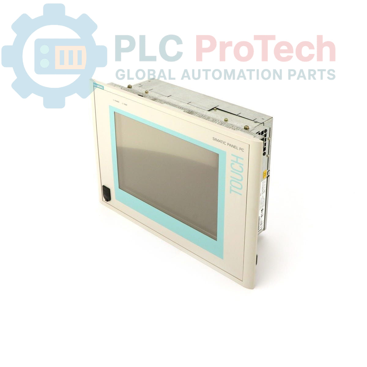
Description
The Siemens 6AV7611-0AA20-0AF0 is a SIMATIC Panel PC 670 designed for industrial control and visualization applications. This unit features a 10-inch TFT display and is powered by an Intel Celeron 300 MHz processor. The standard configuration includes 128 MB of RAM and a 20 GB hard drive, with a pre-installed English version of the Windows 98 operating system. It is engineered to operate on a nominal 24 VDC power supply, making it suitable for integration into standard industrial control panels.
Features
-
10-inch TFT color display for HMI applications.
-
Equipped with an Intel Celeron 300 MHz processor.
-
Includes 128 MB of RAM for application processing.
-
Features a 20 GB hard drive for operating system and data storage.
-
Pre-installed with Windows 98 operating system (English).
-
Designed for a 24 VDC industrial power supply.
Applications
-
Machine control and process visualization.
-
Data acquisition and logging systems.
-
Factory automation control panels.
-
Industrial computing nodes in manufacturing environments.
Technical Specifications
| Specification |
Value |
| Manufacturer |
Siemens |
| Series |
SIMATIC Panel PC 670 |
| Part Number |
6AV7611-0AA20-0AF0 |
| Product Type |
Panel PC |
| Display |
10-inch TFT |
| Processor |
Intel Celeron 300 MHz |
| Memory (RAM) |
128 MB |
| Storage |
20 GB Hard Drive (HD) |
| Operating System |
Windows 98 (English) |
| Power Supply |
24 VDC |
| Lifecycle Status |
Obsolete |
| Shipping Weight |
4.00 kg |
| Commodity Code |
85371091 |
| ECCN |
N |
| Country of Origin |
Germany (Estimated) |
| Package Dimensions (Calculated) |
35 cm x 25 cm x 15 cm |
Installation Guidelines
CRITICAL WARNING: Installation, modification, or removal of this device must be performed only by qualified electrical personnel. Always de-energize the control panel and follow lock-out/tag-out (LOTO) procedures before accessing any internal components. Failure to comply can result in severe injury or death.
-
1
Ensure the main power to the cabinet is disconnected and locked out. Verify the absence of voltage with a properly rated meter.
-
2
Confirm that the panel cutout dimensions match the requirements for the PC 670 chassis. Ensure the mounting surface is clean and flat.
-
3
Carefully insert the Panel PC into the prepared cutout from the front of the panel.
-
4
From the rear, install and tighten the mounting clamps evenly in a cross-pattern to ensure a uniform seal against the panel gasket. Do not overtighten.
-
5
Connect the 24 VDC power supply wiring to the designated terminals, strictly observing correct polarity (+/-).
-
6
Connect the chassis to the panel's protective earth (PE) ground point using a low-impedance conductor.
-
7
Connect all required communication, network, and peripheral cables (e.g., Ethernet, USB, serial).
-
8
After closing the panel door and removing the LOTO device, re-energize the system and verify the Panel PC boots correctly.