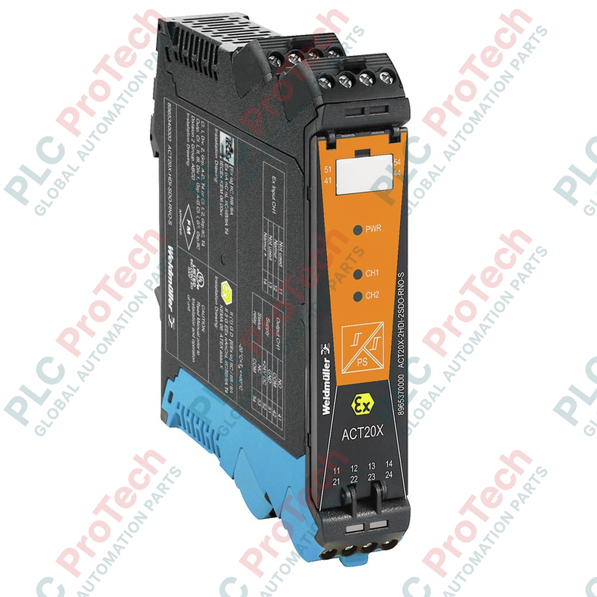
Operating as an intrinsically safe solenoid driver, the Weidmuller ACT20X-SDI-HDO-H-S controls valve systems, acoustic alarms, and indicators located in hazardous areas. This high-performance module provides galvanic isolation between the control system and the field devices, ensuring reliable signal transmission and robust explosion protection in demanding process environments.
Key Features
- Intrinsically safe output (Ex ia IIC) designed for direct deployment in hazardous areas.
- Integrated alarm relay output for immediate signaling of power loss or internal device errors.
- FDT/DTM software-based configuration for precise parameterization and diagnostic monitoring.
- Compact 22.5 mm DIN-rail housing to optimize space within electrical control panels.
- Secure screw connection technology to guarantee long-term, vibration-resistant wiring.
Industrial Applications
- Chemical and petrochemical processing plants with explosive atmospheres (Zone 0, 1, and 2).
- Oil and gas extraction, refining, and distribution facilities.
- Pneumatic and hydraulic solenoid valve control in hazardous process loops.
- Industrial signaling, beacon control, and acoustic alarm integration.
Technical Specifications
| Specification Parameter |
Technical Value |
| Manufacturer |
Weidmuller |
| Article Number (SKU) |
8965410000 |
| Model Designation |
ACT20X-SDI-HDO-H-S |
| Product Type |
Valve Control / Solenoid Driver |
| Number of Channels |
1 |
| Supply Voltage Range |
19.2 to 31.2 V DC |
| Power Consumption |
<= 2.5 W |
| Step Response Time |
<= 10 ms |
| Alarm Functionality |
No supply voltage, Device error |
| Alarm Relay Output |
1 NC contact |
| Nominal Switching Voltage |
<= 125 V AC / 110 V DC |
| Continuous Current (Alarm) |
<= 0.5 A AC / 0.3 A DC |
| Configuration Interface |
FDT/DTM software |
| Connection Type |
Screw connection |
| Protection Degree |
IP20 |
| Operating Temperature |
-20 to +60 degC |
| Ambient Humidity |
0 to 95% (non-condensing) |
| Dimensions (H x W x D) |
117.2 mm x 22.5 mm x 113.6 mm |
| Net Weight |
170 g |
| Shipping Weight (Calculated) |
1.2 kg |
| Country of Origin |
Germany |
Connections and Interfaces
| Terminal Block / Pin |
Functional Assignment |
| Terminals 11, 12 |
Digital Control Input (Safe Area) |
| Terminals 13, 14 |
Alarm Relay Output (NC Contact) |
| Terminals 41, 42 |
Intrinsically Safe Solenoid Output (Hazardous Area, Ex ia) |
| Terminals 51, 52 |
Power Supply Input (19.2 to 31.2 V DC) |
Empirical Engineering Insights
Alternative Models & Compatibility
The ACT20X-SDI-HDO-H-S is fully compatible with standard FDT/DTM frame applications such as Weidmuller WI-Manager. When replacing legacy ACT20X models, ensure that the configuration profile is exported and reloaded using the CBX200 USB interface cable to preserve specific safety loop parameters.
Application Pitfalls & Engineering Notes
When mounting multiple ACT20X modules side-by-side on a DIN rail, ensure cabinet ventilation maintains ambient temperatures below 60 degC. High-density packing without adequate airflow can lead to localized thermal stress. Always verify that the Ex-i output parameters (Uo, Io, Po) strictly match the electrical characteristics of the connected solenoid valve to maintain safety loop integrity.
Commissioning & Wiring Tips
Perform offline configuration via the front-panel port before mounting the unit onto the DIN rail. Ensure that intrinsically safe field wiring (hazardous area) is physically separated from non-intrinsically safe wiring (safe area) by a minimum distance of 50 mm, or utilize physical partitions in compliance with IEC/EN 60079-14 standards.
Installation Guidelines
CRITICAL WARNING:
Isolate all power sources before mounting, wiring, or configuring the device. Failure to de-energize the system prior to installation in hazardous areas can result in electrical arcing, leading to severe equipment damage, explosion, or personal injury.
1
Mount the module vertically onto a standard TS 35 DIN rail, ensuring secure mechanical latching.
2
Connect the intrinsically safe field device wiring to the Ex-designated terminals (Terminals 41 and 42).
3
Wire the control input, alarm relay, and the 24 V DC power supply to the safe-area terminals.
4
Connect the CBX200 USB cable to configure the alarm thresholds and operational parameters via FDT/DTM software.