Product Overview
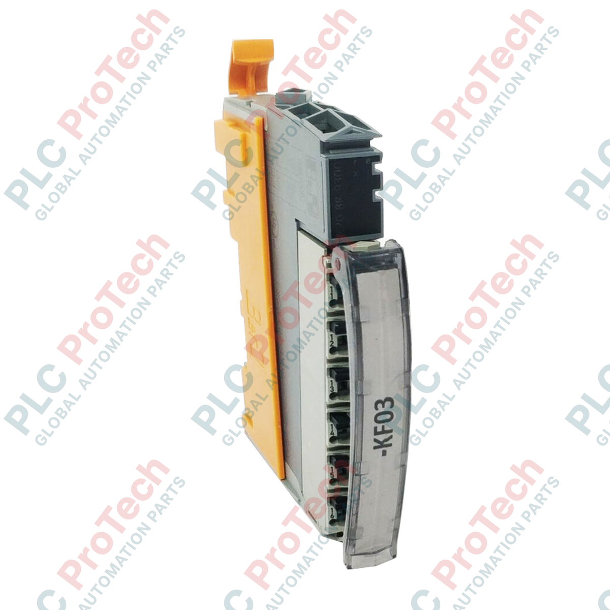
The X20BR9300 (X20BR9300) is a fundamental infrastructure component of the B&R X20 System, serving as the primary bus receiver to interface local I/O segments with the X2X Link backplane. This module provides the essential feed for the X2X Link communication lines and the internal I/O supply, ensuring seamless data flow and power distribution across the terminal block. In large-scale industrial automation layouts—such as distributed control systems in bottling plants, automotive assembly lines, and textile machinery—the X20BR9300 acts as the gateway for remote I/O expansion. By offering electrical isolation between the feed and the X2X Link supply, it protects the system from potential electrical interference, while its support for redundant supply configurations ensures maximum uptime in mission-critical environments.
Technical Configuration
The hardware architecture of the X20BR9300 is designed for specific placement and high reliability. It must be operated exclusively on the slot to the far left of an I/O station to correctly initialize the bus segment. The module integrates a dual-purpose feed mechanism that powers both the internal communication logic and the attached I/O modules. A key feature of this unit is the ability to operate multiple supply modules simultaneously, allowing for redundancy in the X2X Link power supply; if one supply fails, the system continues to operate without interruption. The electrical isolation between the input power and the internal bus logic prevents ground loops and voltage spikes from damaging the sensitive communication architecture. For a complete installation, the module is supplied with both the left and right end plates to ensure proper mechanical termination of the X20 rack.
Technical Specifications
| Feature |
Specification |
| Model |
X20BR9300 |
| Brand |
B&R (Bernecker + Rainer) |
| Module Type |
X2X Link Bus Receiver |
| Function |
Feed for X2X Link and Internal I/O |
| Isolation |
Electrical isolation between feed and bus |
| Redundancy |
Supported (via simultaneous supply modules) |
| Slot Requirement |
Far left slot only |
| Included Accessories |
Left and right end plates |
| Operating Temp |
0 to 55 deg C |
| Protection Rating |
IP20 |
| Shipping Weight |
2.0 kg |
Technical FAQs
Why must the X20BR9300 always be placed in the far left slot?
The far left slot is the hardware-defined entry point for the X2X Link bus. The receiver must occupy this position to correctly establish the electrical termination and signal direction for all subsequent I/O modules in the segment.
Can I use two X20BR9300 modules in a single segment for power redundancy?
Yes. By operating multiple supply modules simultaneously, the X2X Link supply becomes redundant. If one module loses its input feed, the other modules will maintain the bus voltage, preventing a communication timeout and system halt.
What is the purpose of the electrical isolation in this receiver?
The isolation separates the external 24 VDC supply from the internal logic voltage used by the X2X Link. This barrier prevents field-side electrical noise or faults from entering the backplane, ensuring stable data transmission across long distances.
Engineering & Installation Guide
-
Mechanical Termination: Always install the included left and right end plates. The end plates are not merely cosmetic; they provide the necessary mechanical tension to keep the X20 modules securely mated and protected from environmental dust that could cause intermittent contact issues.
-
Redundant Power Wiring: When configuring for redundancy, ensure that both power feeds originate from stable, industrial-grade power supplies. It is recommended to use the same voltage potential for both feeds to ensure balanced current sharing across the redundant modules.
-
X2X Link Distance: While the X20BR9300 facilitates the connection, the maximum distance between X2X Link stations is typically 100 meters. For segments approaching this limit, ensure the use of high-quality shielded twisted-pair cables and verify that the bus receiver is correctly grounded to the DIN rail to maintain signal integrity.