Description
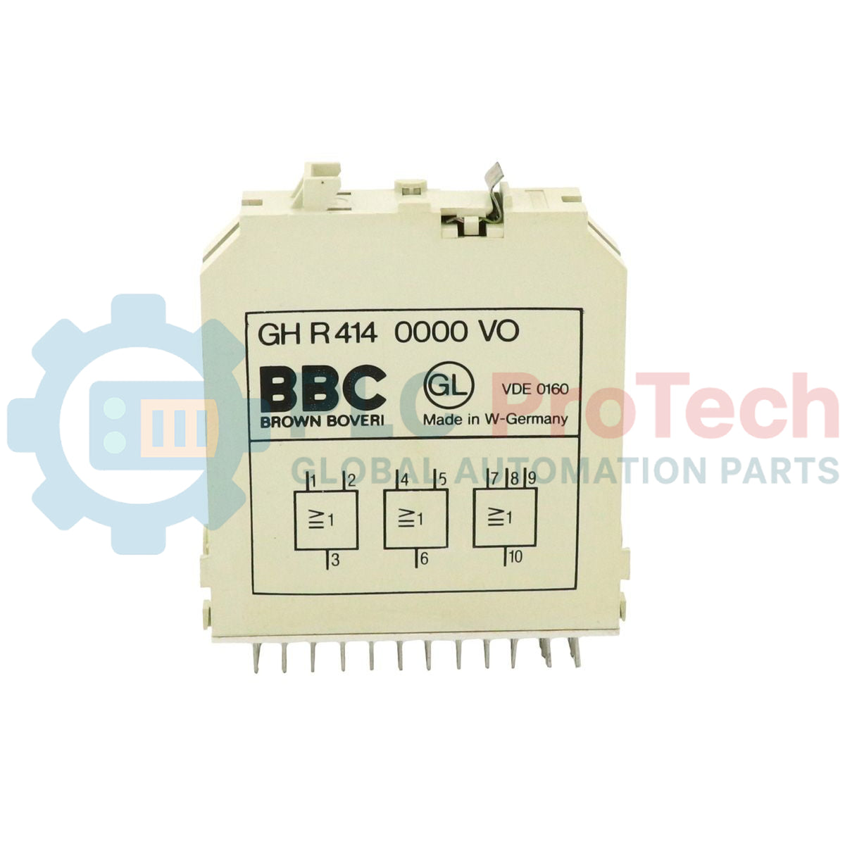
Executing hardware-level logic operations within the legacy Procontic control architecture, the ABB GHR4140000VO provides robust signal gating without software processing overhead. This passive industrial logic module is engineered with three independent OR gate circuits designed to consolidate control signals, interlocks, and permissive loops in high-reliability systems. Because the signal paths are non-amplified, the module functions with zero current draw from the system power supply, making it an exceptionally stable and fail-safe component for discrete industrial logic control panels.
Features
-
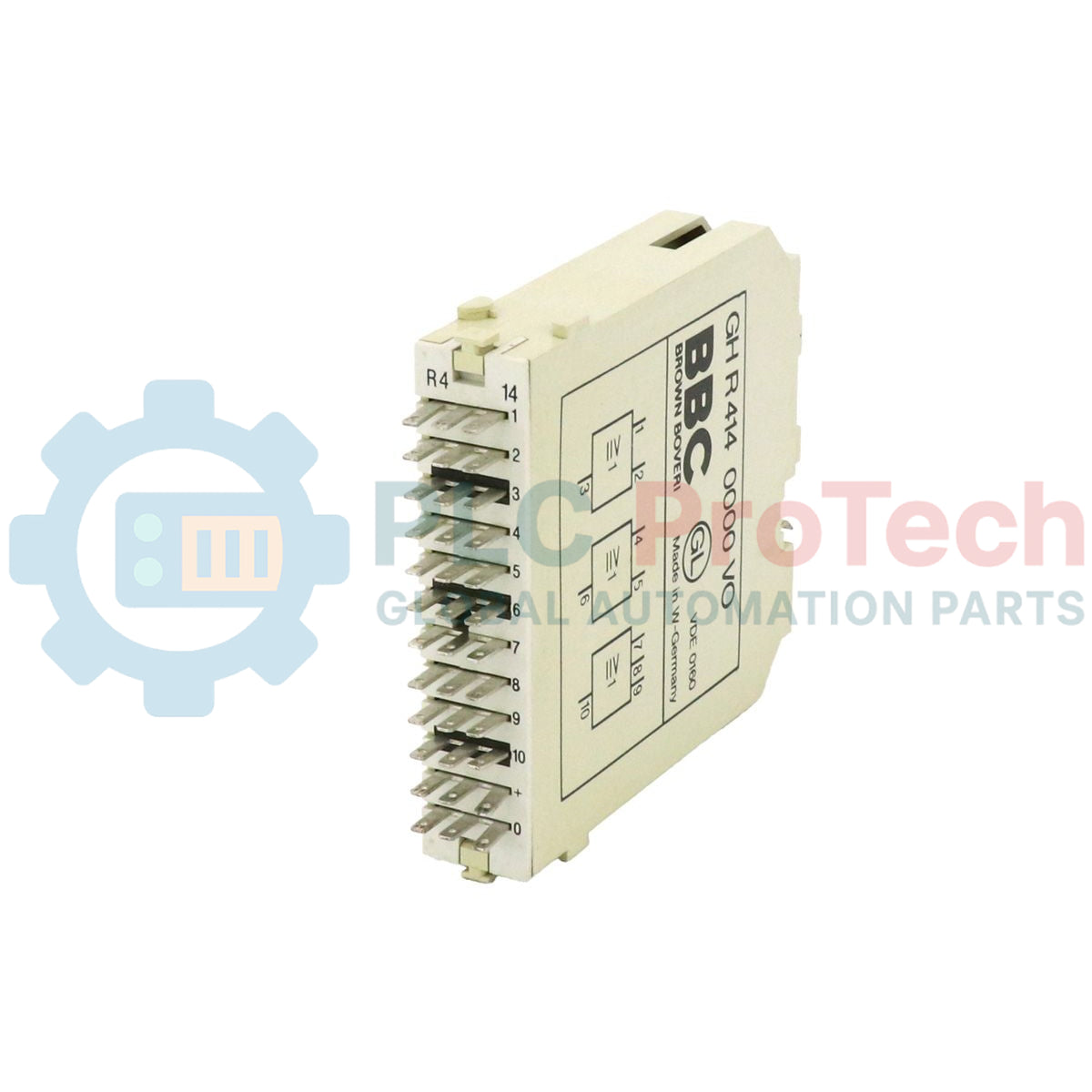
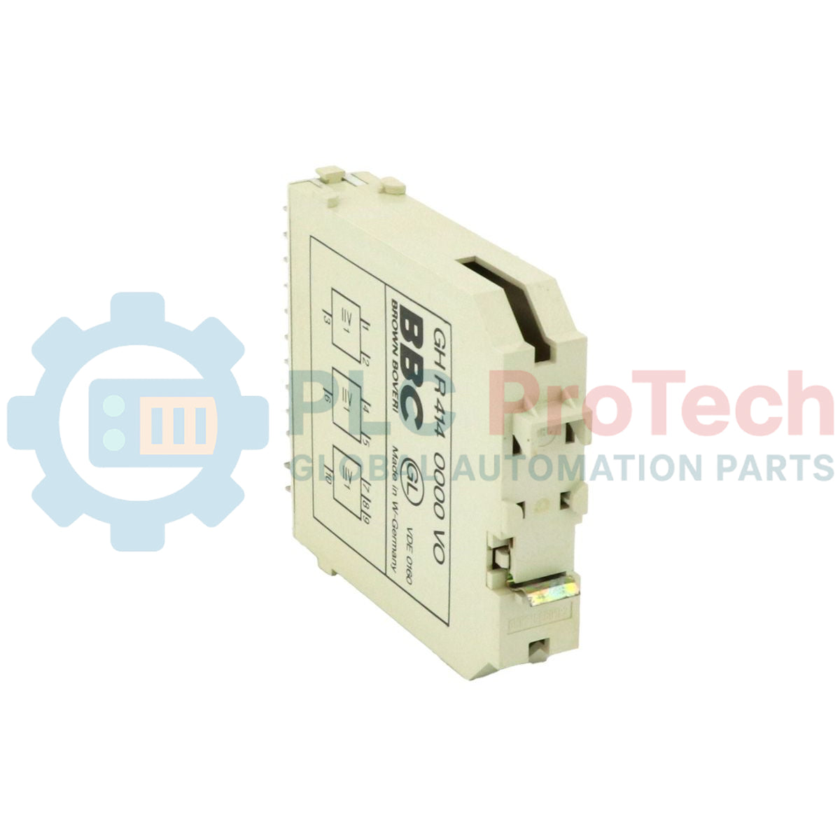
Independent Gating Circuits: Features three isolated OR functions, providing two 2-input gates and one 3-input gate on a single physical module.
-
Passive Signal Path: Operates entirely on input signal power with zero internal power supply burden.
-
Zero Propagation Delay: Real-time hardware switching logic with no digital processing or software scanning latency.
-
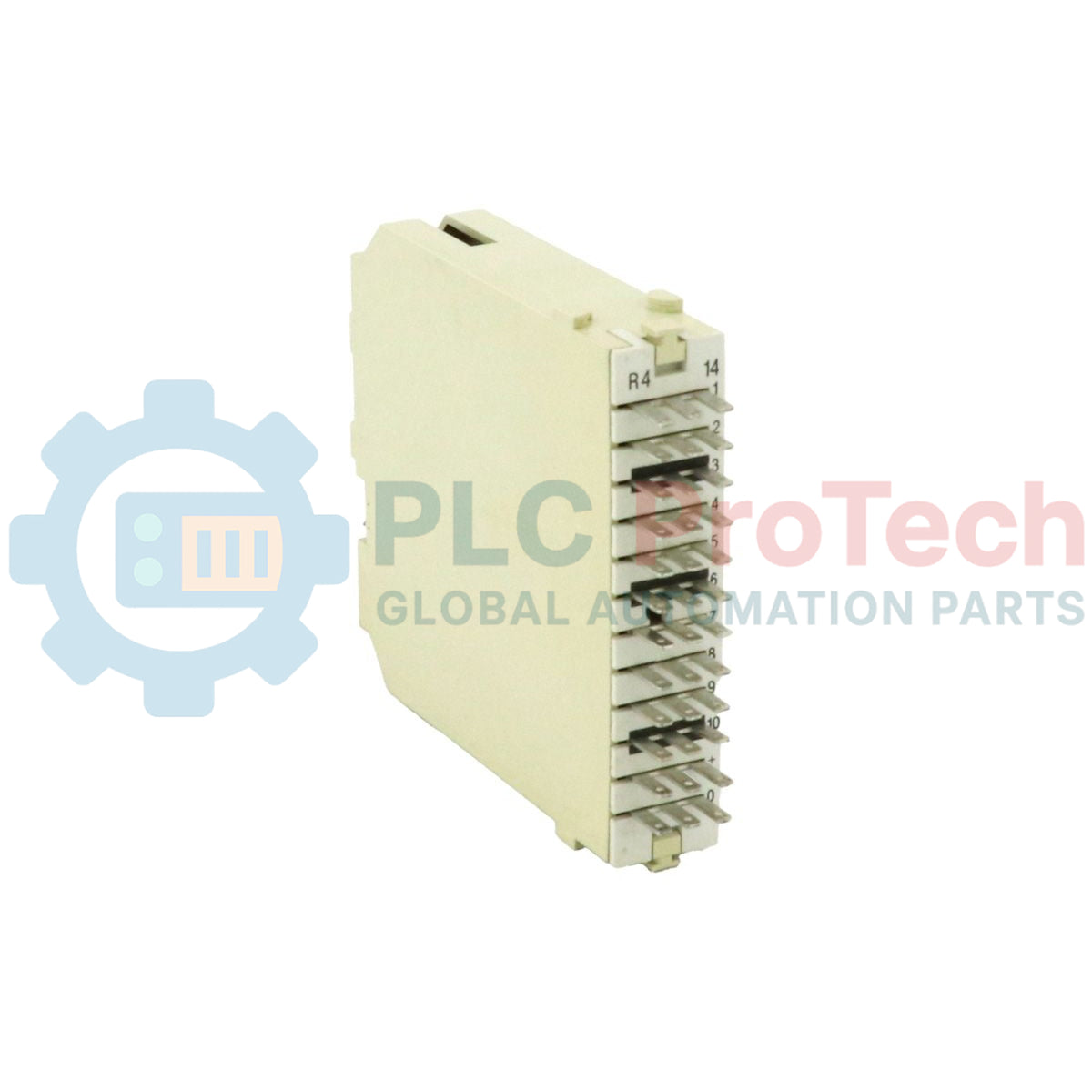
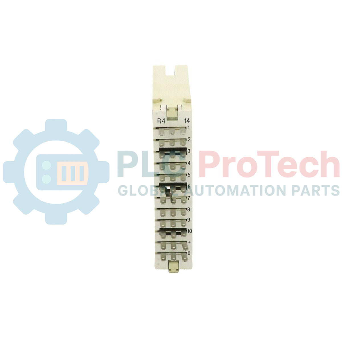
High-Density Integration: Housed in a compact single-width format for efficient mounting within standard ABB Procontic racks.
-
Standardized Visual Coding: Distinct black visual identifier for rapid card-type classification during maintenance cycles.
Applications
- Legacy ABB Procontic PLC system retrofits and hardware logic interlocking.
- Multi-station emergency shutdown (ESD) systems and permissive start-up loops.
- Hardwired signal concentration and voting logic arrays.
Ordering Information
| Order Item Description |
Order Code / Part Number |
| GHR4140000VO Module |
GH R414 0000 V0 |
| Circuit Symbol Transparency |
GH R700 1901 R3 |
| Application Reference Documentation |
D GEF 31014 D |
Technical Specifications
| Parameter / Specification |
Value / Rating |
| Manufacturer |
ABB |
| Model Number |
GHR4140000VO |
| Series |
Procontic |
| Gate Configuration |
2 x 2-Input OR Gates, 1 x 3-Input OR Gate |
| Logic Formula |
Q = A OR B OR C |
| Nominal Circuit Voltage |
24 VDC |
| Max. Series Cascade |
4 Modules (at 24 VDC nominal) |
| Signal Amplification |
None (Passive module) |
| Module Power Consumption |
0 mA (Zero burden on control supply voltage) |
| Propagation Delay |
Undelayed (instantaneous hardware response) |
| Identifying Module Color |
Black |
| Mechanical Form Factor |
Single width |
| Shipping Weight (Calculated) |
0.11 kg |
| Package Dimensions (Calculated) |
13.5 x 8.0 x 2.2 cm |
Alternative Models & Compatibility
The GHR4140000VO logic module is fully backwards-compatible with standard ABB Procontic mounting frames and connector backplanes. If sourcing drop-in replacements, ensure that the mechanical coding pins on the chassis match the single-width configuration of this black-coded component. When replacing legacy active logic units with this passive module, confirm that upstream transmitters have appropriate output driving specifications.
Application Pitfalls & Engineering Notes
Because this logic module is completely passive and contains no internal signal amplification, cascading more than 4 gates in a single serial chain with 24 VDC can lead to excessive signal attenuation. Ensure downstream receivers can accurately detect the logic-high threshold despite cumulative series voltage drops. Additionally, note that input loading calculations must account for the sum total of downstream destination loads linked to the output channel.
Commissioning & Wiring Tips
Always verify signal source impedances during initial setup. High-impedance sensors or low-power solid-state outputs may struggle to drive multiple parallel inputs on passive OR gates. We recommend using shielded twisted-pair cabling for remote logic routing to avoid high-frequency noise injection on passive lines, which could lead to false logic-high triggers at high-speed receiving terminals.
Installation Guidelines
CRITICAL WARNING
De-energize all connected input and output control loops before inserting or extracting the logic module from the Procontic backplane. Hot-plugging passive modules can cause transient voltage spikes, leading to false-triggering of adjacent hardware interlocking circuitry.
1
Verify that the backplane slot is clean, free of debris, and matches the single-width spacing profile of the module.
2
Align the edge-card connectors carefully with the backplane receptacle and slide the unit steadily until the card is fully seated.
3
Secure any retention screws or mechanical latches to protect against severe cabinet vibration.
4
Power on individual input logic feeds one by one to verify output logic switching behavior locally at the terminals.