Description
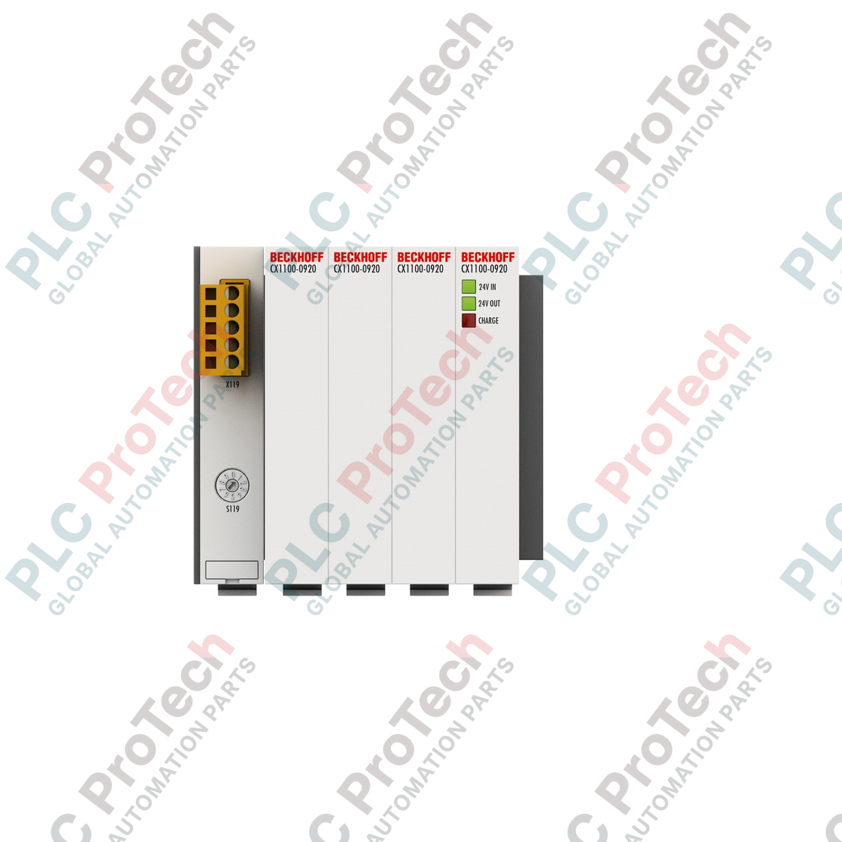
Providing short-term backup power for orderly system shutdowns, the Beckhoff CX1100-0920 is an integrated capacitive UPS module engineered for direct system bus integration with CX series Embedded PCs. Operating via a 16-bit ISA PC/104 standard system interface, this hardware module prevents critical data loss during sudden mains failure by supplying buffered energy directly to the host CPU. By utilizing durable ultra-capacitors instead of electrochemical battery chemistry, the unit delivers maintenance-free operation and high thermal tolerance in demanding industrial environments.
Features
-
Capacitive Storage Technology: Maintenance-free energy storage using gold-capacitors, eliminating chemical wear and battery aging.
-
Integrated PC/104 Interface: Seamless 16-bit ISA data and power connection directly to the embedded controller stack.
-
Adjustable Retention Time: Load-dependent backup windows configurable through system software control to match specific CPU shutdown cycles.
-
Visual Diagnostic Array: On-board LEDs providing real-time status indication for 24 V DC input, 24 V DC output, and charging status.
Applications
-
Persistent Data Saving: Ensuring TwinCAT persistent variable registries are fully written to non-volatile flash memory during power dropouts.
-
Orderly Machine Stop: Driving critical low-current control circuits to bring active machinery to a safe physical state before complete CPU power-down.
-
Unstable Power Grids: Buffering micro-interruptions and voltage sags in industrial processing plants without system reboots.
Technical Specifications
| Parameter |
Value / Specification |
| Manufacturer |
Beckhoff Automation |
| Model Number |
CX1100-0920 |
| Input Supply Voltage |
24 V DC (-15% / +20%) |
| Energy Storage Medium |
Capacitive (Ultra-capacitors) |
| Energy Capacity |
40 As (Ampere-seconds) |
| Maximum Output Current |
1.1 A at 24 V DC |
| Maximum Charging Current |
4.0 A |
| Maximum Power Loss |
2 W |
| Interface Standard |
16-bit ISA (PC/104 standard) |
| Protection Rating |
IP20 |
| Operating Temperature |
0 to +55 degC |
| Storage Temperature |
-25 to +85 degC |
| Relative Humidity Range |
95% maximum, non-condensing |
| Standards & Approvals |
CE, EN 61000-6-2 (Immunity), EN 61000-6-4 (Emission) |
| Vibration / Shock Resistance |
Conforms to EN 60068-2-6 / EN 60068-2-27 |
| Dimensions (W x H x D) |
95 mm x 100 mm x 91 mm |
| Net Unit Weight |
617 g |
| Shipping Weight (Calculated) |
2.0 kg |
Empirical Engineering Insights
Alternative Models & Compatibility
The CX1100-0920 is purpose-built to align within Beckhoff CX1010, CX1020, and CX1030 Embedded PC hardware configurations. It is not compatible with newer CX2000 multi-core series architectures, which utilize differing bus layouts and power supply coupling mechanisms. Always verify your existing CPU connection header pins match the PC/104 16-bit physical bus spacing before locking the stack modules together.
Application Pitfalls & Engineering Notes
Capacitive storage units like the CX1100-0920 have a linear voltage discharge curve compared to chemical batteries. With a capacity of 40 As, the actual retention backup time is highly load-dependent. When running a maximum system load of 1.1 A, power is held for approximately 36 seconds. Systems must be configured within the TwinCAT software interface to trigger the write-to-disk persistent cycle immediately upon mains failure detection. Running external, non-CPU bus powered peripherals directly from the same 24 V DC line during an outage can rapidly deplete capacitive reserves before write sequences complete.
Commissioning & Wiring Tips
During initial commissioning, the module requires up to 4.0 A of charging current to energize the internal ultra-capacitor cells from a discharged state. Ensure the system primary power supply is sized with sufficient overhead to handle this transient inrush alongside standard operational load profiles. Check that the on-board LED diagnostics show a steady "Charge" light indicating complete capacitive cell charge before activating persistent file writes in the control logic.
Installation Guidelines
CRITICAL WARNING: De-energize all primary and auxiliary power sources before handling the module stack. Capacitive components inside this module can retain electrical potential even after mains power is disconnected. Verify voltage potential is fully discharged before joining or separating system bus modules to prevent physical ESD destruction of internal ISA interface electronics.
1
Align Module Contacts:
Inspect the PC/104 interface connectors on the side of the CX Embedded PC and the module. Carefully slide the module onto the system's mounting rail, guiding the male pins straight into the matching female sockets.
2
Secure the Rail Lock:
Engage the mechanical rail retention latch on the bottom of the module enclosure to prevent shifting or contact loss from system vibration.
3
Establish Grounding and Power:
Connect the power supply wiring to the 24 V DC terminals using high-quality shielded cabling. Ensure the DIN-rail connection is properly bonded to functional ground (FE) for transient noise rejection.