Description
Designed for integration into standard K-bus networks, the Beckhoff KL4022 enables high-precision processing of current loop control signals. This terminal converts 12-bit digital values from the automation controller into isolated analog current outputs within the standard 4 to 20 mA range. Its single-ended topology, compact housing, and low conversion latency make it highly suitable for demanding industrial actuator control, valve positioning, and motor drive setpoint configuration.
Features
- Dual-channel analog output configuration utilizing single-ended common ground architecture.
- Robust 12-bit digital-to-analog conversion delivering dependable loop precision.
- High-integrity electrical isolation of 500 V between the internal K-bus and field signals.
- Rapid internal conversion sequence with a typical processing time of 1.5 milliseconds.
- Efficient power distribution leveraging integrated 24 V DC power contacts on the backplane.
Applications
- Electro-pneumatic and electro-hydraulic proportional valve positioners.
- Frequency inverter and variable speed drive (VSD) speed references.
- Distributed SCADA and process control instrumentation interfaces.
- Industrial boiler and heating element loop controller feedback.
Technical Specifications
| Parameter |
Value / Rating |
| Manufacturer |
Beckhoff Automation |
| Model Number |
KL4022 |
| Signal Range |
4 to 20 mA |
| Number of Channels |
2 |
| Resolution |
12-bit |
| Load Impedance |
Less than 500 Ohm |
| Conversion Time |
approx. 1.5 ms |
| Output Error |
Less than +/- 0.1% (relative to full-scale value) |
| Power Supply |
24 V DC via power contacts (or 15 V DC via KL9515 supply terminal) |
| K-Bus Current Consumption |
typ. 75 mA |
| Electrical Isolation |
500 V (K-bus / signal voltage) |
| Operating Temperature |
-25 to +60 degC |
| Storage Temperature |
-40 to +85 degC |
| Relative Humidity |
95%, non-condensing |
| Country of Origin |
Germany |
| Weight |
approx. 80 g |
| Shipping Weight (Calculated) |
0.25 kg |
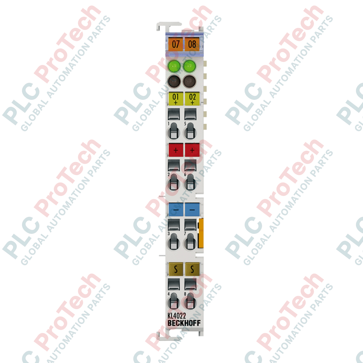
Connections and Interfaces
| Terminal Point |
Signal Assignment |
Description |
| 1 |
OUT 1 |
Analog Output Channel 1 (+) |
| 5 |
0V (1) |
Analog Output Channel 1 ground (-) |
| 2 |
OUT 2 |
Analog Output Channel 2 (+) |
| 6 |
0V (2) |
Analog Output Channel 2 ground (-) |
| 3 |
+24 V |
Power Contact Connection (+24 V DC) |
| 7 |
0 V |
Power Contact Connection (0 V DC) |
| 4 |
Shield |
Shield contact point (connected to DIN rail) |
| 8 |
Shield |
Shield contact point (connected to DIN rail) |
Empirical Engineering Insights
Alternative Models & Compatibility
The KL4022 utilizes Beckhoff's legacy K-bus backplane communication system. If transitioning to an EtherCAT infrastructure, the direct equivalent is the EL4022. Note that EL-series terminals utilize the E-bus and cannot reside on standard KL-series couplers (e.g., BK9000, BK3120) without active E-bus/K-bus converter couplers.
Application Pitfalls & Engineering Notes
Since the KL4022 is a single-ended terminal sharing a common internal ground loop, noise injected into the 0 V signal reference on one loop can cause cross-talk or offset drift on the secondary channel. For field installations with significant ground potential differences, isolated signal conditioning barriers must be installed between the KL4022 and the end-actuator to prevent loop degradation.
Commissioning & Wiring Tips
Ensure that shielding is correctly terminated. Terminal points 4 and 8 are connected to the mounting rail. To guarantee sufficient noise rejection, the standard 35 mm DIN rail must be connected to the central control cabinet ground with low-impedance copper braided strap. Ensure K-bus power contacts are adequately populated with 24 V DC; voltage drops below 18 V DC will cause conversion errors or terminal fault signals within TwinCAT.
Installation Guidelines
CRITICAL WARNING: ELECTRICAL HAZARD
Isolate and lock out all power supplies to the system before inserting or removing K-bus components. Modifying the physical configuration or terminal assembly while the power is active can induce voltage spikes, resulting in damage to the internal bus driver circuitry or physical terminal contacts.
1
Mount the terminal onto the 35 mm DIN rail (EN 60715) by sliding the terminal's rear slot onto the rail guide until the locking tab audibly clicks.
2
Align the terminal laterally with the adjacent Bus Terminal block to engage the tongue-and-groove joint and establish continuous electrical contact via the side-mounted gold contacts.
3
Insert field connection cables into the cage-clamp connectors using an appropriate industrial screwdriver. Release the mechanism to secure wire connection.
4
Connect the analog loop shielding directly to contacts 4 or 8 to guarantee direct path grounding through the DIN rail structure.