Description
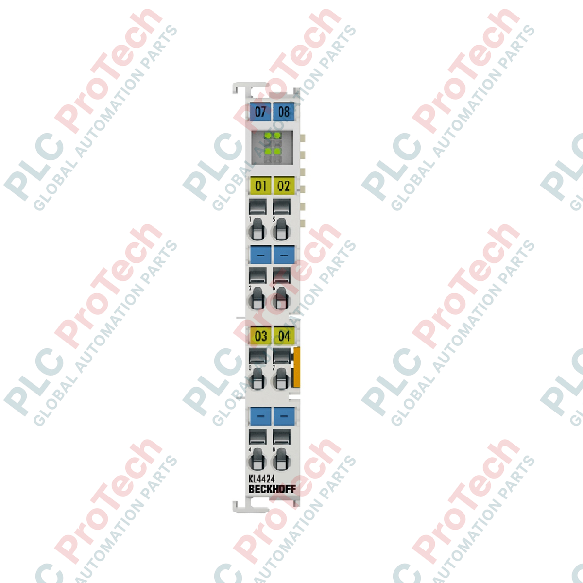
Generating precise analog control signals within the Beckhoff I/O framework, the Beckhoff KL4424 operates as a high-density, four-channel current output module. Engineered to process signals in the standard 4 to 20 mA range, this terminal delivers high resolution and galvanic isolation to field-level actuators, control valves, and current-loop indicators. Its robust design is optimized for environments demanding dependable noise immunity and stable performance under fluctuating thermal conditions.
Key Features
-
Four Single-Ended Channels: Compact integration of four analog outputs within a single 12 mm Bus Terminal housing.
-
12-Bit Resolution: High-precision digital-to-analog conversion providing precise process control execution.
-
Short-Circuit Proof: Outputs are protected against wiring faults and load fluctuations up to 350 Ohms.
-
Flexible Power Options: Operates natively via 24 V DC power contacts, with support for 15 V DC via the KL9515 power supply terminal.
-
Galvanic Isolation: Provides 500 V isolation between the internal K-bus electronics and the signal channels.
-
Comprehensive Certifications: Approved for hazardous areas with ATEX, IECEx, and cFMus Class I Division 2 ratings.
Applications
- Modulating valve positioners and pneumatic actuators in oil and gas refineries.
- Variable frequency drive speed reference control over standardized current loops.
- Process instrumentation control in chemical processing plants.
- Water and wastewater flow rate configuration systems.
Technical Specifications
| Parameter |
Value / Specification |
| Manufacturer |
Beckhoff Automation |
| Model Series |
KL-Bus Terminal System (KL4xxx) |
| Number of Outputs |
4 single-ended |
| Signal Current Range |
4...20 mA |
| Resolution |
12-bit |
| Output Load Limitation |
< 350 Ohm (short-circuit proof) |
| Output Error |
< ±0.1% (relative to end-scale value) |
| Conversion Time |
approx. 4 ms |
| Supply Voltage |
24 V DC via power contacts (or 15 V DC via KL9515) |
| Current Consumption (K-bus) |
typ. 20 mA |
| Current Consumption (Power Contacts) |
typ. 60 mA + load current |
| Electrical Isolation |
500 V (K-bus / signal voltage) |
| Bit Width in Process Image |
4 x 16-bit output data (optional 4 x 8-bit control/status) |
| Operating Temperature |
0 degC to +55 degC |
| Storage Temperature |
-25 degC to +85 degC |
| Relative Humidity |
95%, non-condensing |
| Vibration/Shock Resistance |
Conforms to EN 60068-2-6 / EN 60068-2-27 |
| EMC Immunity/Emission |
Conforms to EN 61000-6-2 / EN 61000-6-4 |
| Protection Rating |
IP20 (variable installation position) |
| Net Weight |
approx. 75 g |
| Shipping Weight (Calculated) |
0.15 kg |
| Package Dimensions (Calculated) |
12.0 x 7.0 x 3.0 cm |
| Hazardous Location Approvals |
ATEX II 3 G Ex nA IIC T4 Gc / IECEx Ex ec IIC T4 Gc / cFMus Cl. I Div 2 |
Connections and Interfaces
| Terminal Point |
Signal Name |
Description |
| 1 |
Out 1 |
Analog Output 1 (4...20 mA) |
| 2 |
Out 2 |
Analog Output 2 (4...20 mA) |
| 3 |
Out 3 |
Analog Output 3 (4...20 mA) |
| 4 |
Out 4 |
Analog Output 4 (4...20 mA) |
| 5 |
0 V |
Common Ground Reference (Power Contact) |
| 6 |
0 V |
Common Ground Reference (Power Contact) |
| 7 |
0 V |
Common Ground Reference (Power Contact) |
| 8 |
0 V |
Common Ground Reference (Power Contact) |
Alternative Models & Compatibility
The terminal utilizes standard K-bus backplane communication and can be combined seamlessly with other standard bus terminals. For installations requiring pluggable wiring harnesses to minimize field maintenance times, the KS4424 version serves as the direct hardware equivalent featuring pluggable connector blocks.
Application Pitfalls & Engineering Notes
When sizing current loops, ensure that the total loop resistance does not exceed 350 Ohms. Exceeding this limit will cause the output driver to saturate before reaching the full 20 mA signal level, resulting in non-linear control. In high-density cabinet layouts with elevated ambient operating temperatures, consider powering the terminal at 15 V DC using a KL9515 terminal block to minimize local thermal dissipation within the enclosure.
Commissioning & Wiring Tips
To protect sensitive low-level analog signals from electromagnetic interference, use shielded twisted-pair (STP) cabling for all output runs. Ground the cable shield only at the entry point of the control cabinet to avoid forming ground loops. Ensure that the 0 V reference terminals (5 through 8) are properly bridged to the common power contact ground path to prevent common-mode voltage offsets on the analog signals.
Installation Guidelines
CRITICAL WARNING:
De-energize all field circuits and system power supplies before mounting or dismounting the terminal. Inserting or removing bus terminals while the backplane or external field power is energized can cause physical damage to the internal K-bus contacts and compromise surrounding modules.
1
Mounting on DIN Rail
Snap the module onto a standard 35 mm DIN rail (EN 60715), ensuring that the locking mechanism engages securely with the rail's edges.
2
Side-by-Side Integration
Slide the terminal horizontally along the DIN rail to interconnect the K-bus and power contacts with adjacent terminals. Verify that the side tongue-and-groove joints are fully locked.
3
Field Wiring Termination
Insert wire connections using a screwdriver to open the spring-loaded tension clamps. Ensure only stripped conductors without frayed copper strands are inserted, then release the spring clamp to lock the connection.