Description
Acquisition of high-precision temperature measurements in industrial automation environments is handled directly by the Beckhoff KS3222, a 2-channel analog input terminal designed for resistive sensors. The Beckhoff KS3222 enables direct connection of resistance thermometers, including Pt100, Pt1000, Ni100, and Ni1000 sensors, utilizing a highly stable 4-wire connection technology to eliminate errors from line resistance. This terminal features pluggable wiring levels, making it highly serviceable for modular control cabinets using the Beckhoff K-bus system. Featuring built-in open-circuit recognition and a dedicated 50 Hz filter, this module ensures reliable signal integrity and high-resolution temperature conversion in harsh industrial environments.
Features
-
Dual-Channel Input: Supports two independent RTD or resistance measurement sensors.
-
Pluggable Wiring Level: The KS series housing allows pre-wired terminal blocks to be plugged or unplugged easily for rapid commissioning and maintenance.
-
4-Wire Connection Technology: Minimizes line resistance measurement errors for elevated precision over long cable runs.
-
Broad Sensor Compatibility: Direct integration of Pt100, Pt200, Pt500, Pt1000, Ni100, Ni120, Ni1000, KTY, and potentiometer measurements.
-
High-Resolution Digitization: Provides a 0.01 degC resolution per digit with a fast typical conversion time of 50 ms.
-
Robust Electrical Isolation: Delivers 500 V electrical isolation between the K-bus and the signal channels.
-
Hazardous Location Certified: ATEX Zone 2 Ex marking (II 3 G Ex nA IIC T4 Gc) for explosive environments.
Applications
-
Precision Temperature Control: Heat treatment, plastics processing, and industrial furnace monitoring.
-
Process Engineering: Chemical processing plants requiring ATEX-certified temperature acquisition.
-
HVAC and Climate Automation: Environmental monitoring in data centers and storage facilities.
-
Mechanical Engineering: Integrated temperature sensing for motor windings, bearings, and hydraulic systems.
Technical Specifications
| Parameter |
Specification |
| Manufacturer |
Beckhoff |
| Model |
KS3222 |
| Number of Inputs |
2 |
| Technology / Connection |
4-wire connection |
| Power Supply |
Via the K-bus |
| K-Bus Current Consumption |
Typical 60 mA |
| Compatible Sensors |
Pt100, Pt200, Pt500, Pt1000, Ni100, Ni120, Ni1000, KTY, Resistance (10 Ohm to 1.2/5 kOhm) |
| Measuring Range (Pt) |
-200 to +850 degC |
| Measuring Range (Ni) |
-60 to +250 degC |
| Conversion Time |
Typical 50 ms |
| Measuring Current |
Typical 0.5 mA |
| Resolution |
0.01 degC per digit |
| Measuring Error |
0.1 degC at 40 degC ambient temperature (4-wire, Pt100, 50 Hz filter) |
| Electrical Isolation |
500 V (K-bus / signal voltage) |
| Process Image Bit Width |
Input: 2 x 16-bit data (2 x 8-bit control/status optional) |
| Diagnostics |
Open-circuit / wire-break recognition |
| Operating Temperature |
0 to +55 degC (no condensation, 95% relative humidity) |
| Storage Temperature |
-25 to +85 degC |
| Protection Rating |
IP20 |
| Approvals |
CE, UL, ATEX (II 3 G Ex nA IIC T4 Gc) |
| Housing Material |
Polycarbonate, DIN rail mount (35 mm, EN 60715) |
| Dimensions (W x H x D) |
12 mm x 100 mm x 68 mm |
| Net Weight |
0.07 kg |
| Shipping Weight |
2.00 kg |
Wiring Connection Specifications
| Connection Method |
Pluggable Tension Clamp (Spring Actuation via Screwdriver) |
| Solid Wire Cross-Section |
0.08 to 1.5 mm² (AWG 28 to 16) |
| Stranded Wire Cross-Section |
0.08 to 1.5 mm² (AWG 28 to 16) |
| Fine-Stranded Wire Cross-Section |
0.14 to 1.5 mm² (AWG 26 to 16) |
| Stripping Length |
9 to 10 mm |
| Max. Power Contact Current Load |
10 A |
Empirical Engineering Insights
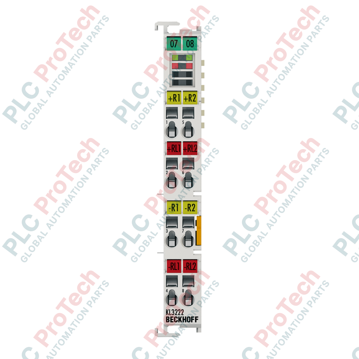
Alternative Models & Compatibility
The KS3222 is functionally identical to the standard Beckhoff KL3222. The key structural difference lies in the connection interface: the KS3222 features a pluggable wiring level, allowing the terminal block connector to be removed while retaining field wiring. This minimizes downtime during physical module replacement. This terminal requires a standard K-bus backplane and can be integrated seamlessly with any Beckhoff BK-series or BC-series Bus Couplers without modifying PLC code or TwinCAT configurations.
Application Pitfalls & Engineering Notes
To ensure high-precision readings down to 0.01 degC, the measuring current is kept at a low typical rate of 0.5 mA. This design constraint is essential to minimize the self-heating of small-mass RTD sensors (such as Pt100) within the medium. However, because the measuring current is low, the signal path is more susceptible to high-frequency electromagnetic interference. When routing RTD wiring through the same cable tray as variable frequency drives (VFDs) or heavy inductive loads, you must utilize shielded twisted pair (STP) cables to avoid signal degradation.
Commissioning & Wiring Tips
When configuring the KS3222 under TwinCAT (2.x or 3.x), the sensor type must be matched to the register settings of the terminal. The factory default setting is optimized for Pt100 sensors. If you are using Ni100 or potentiometer modes, ensure you execute the configuration via register communication (e.g., using KS2000 software or PLC blocks) before putting the loop into auto-control. For 4-wire configuration, ensure all four pins are properly jumpered directly at the RTD sensor element rather than at the control cabinet terminal block to compensate fully for lead wire resistance.
Installation Guidelines
CRITICAL WARNING
Before installing, removing, or wiring any Bus Terminal, isolate the primary power supply of both the field device and the Bus Coupler. Failure to completely de-energize the assembly can cause unexpected diagnostic faults on the K-bus backplane or damage the delicate internal electronic components of adjacent terminals.
1
DIN Rail Alignment: Position the KS3222 onto the 35 mm DIN rail (EN 60715). Slide the unit along the rail until the tongue-and-groove side guides lock securely into the neighboring terminal.
2
Mechanical Lock: Push the terminal assembly firmly toward the DIN rail until you hear the mounting release lock latch engage. Verify mechanical stability.
3
Pluggable Wiring Block: Insert the pre-wired KS plug block into the housing interface, ensuring physical alignment before pressing it home. Secure the wires using the spring tension clamps with a standard flat-head screwdriver.
4
Shield Grounding: Terminate the sensor cable shields to a dedicated low-impedance ground rail positioned close to the entry point of the control panel to minimize EM noise.