Description
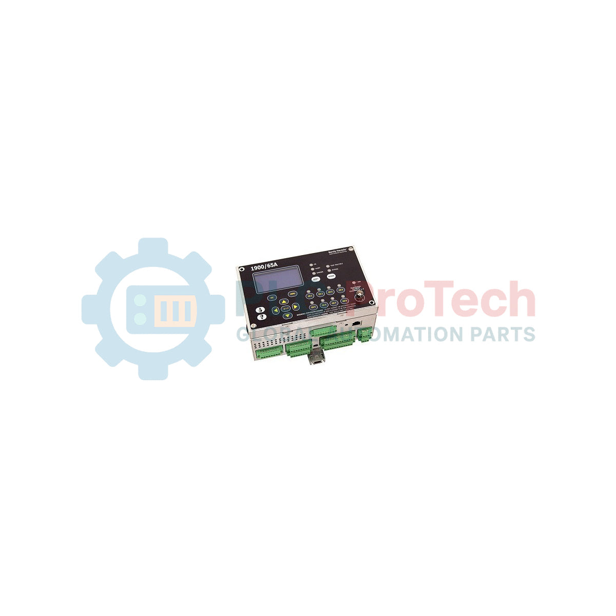
Providing dedicated, continuous machinery protection in space-constrained or standalone applications, the Bently Nevada 1900/65A functions as a self-contained, four-channel general-purpose monitor. This system is engineered to track critical dynamic variables such as vibration, velocity, acceleration, or shaft displacement, alongside direct temperature inputs. This specific configuration, model number 1900/65A-01-01-02-00-00, integrates an AC/DC universal power supply, an attached display module, expanded relay/recorder outputs, and Modbus communications. By processing sensor signals directly at the machine face, it delivers instantaneous alarm and trip capabilities to prevent catastrophic mechanical failures.
Features
- Four configurable transducer channels supporting proximity probes, accelerometers, or velocity sensors.
- Four dedicated temperature channels compatible with RTDs and Type E, J, K, or T thermocouples.
- Six programmable SPDT relay outputs for flexible trip-multiply and alarm voting configurations.
- Four 4 to 20 mA analog outputs for direct PLC/DCS chart recording integration.
- Integrated display interface providing real-time channel readings, alarm statuses, and system diagnostics.
- Dual Modbus communications supporting both Modbus RTU (serial) and Modbus TCP/IP (Ethernet) protocols.
Applications
- Balance-of-plant machinery monitoring including cooling tower fans, industrial blowers, and air handlers.
- Continuous vibration tracking for centrifugal and positive displacement water pumps.
- Thermal and dynamic oversight of large-frame electric induction motors.
- Protection of small reciprocating and screw-type gas compressors.
Ordering Information
| Option Code |
Description |
Configured Status |
| 01 |
Power Option: 85 to 264 Vac (50/60 Hz) / 120 to 370 Vdc |
Included |
| 01 |
Display Option: Combined Display/Modbus/RTD/TC module (Attached) |
Included |
| 02 |
I/O Option: 6 Relays, 4 Recorder Outputs, Modbus RTU & TCP |
Included |
| 00 |
Approvals: Non-Hazardous Area (Standard) |
Included |
| 00 |
Mounting Option: Standard Panel/Wall Mount bracket |
Included |
Technical Specifications
| Manufacturer |
Bently Nevada |
| Model Series |
1900 Series |
| Supply Voltage Range |
85 to 264 Vac, 47 to 63 Hz, or 120 to 370 Vdc |
| Dynamic Signal Inputs |
4 Channels (Supports Proxmitiy, Acceleration, or Velocity transducers) |
| Transducer Power Output |
-24 Vdc, up to 40 mA per channel |
| Temperature Sensor Support |
3-wire platinum RTD (100 ohm), Type J, K, T, or E Thermocouples |
| Relay Contact Rating |
SPDT, 5 A at 250 Vac / 5 A at 30 Vdc (resistive load) |
| Ethernet Port |
10/100 Base-T (Modbus TCP/IP, configuration port) |
| Operating Temperature |
-20 to +70 degC (-4 to +158 Fahrenheit) |
| Country of Origin |
United States |
| Shipping Weight (Calculated) |
2.5 kg (5.5 lbs) |
| Package Dimensions (Calculated) |
280 x 220 x 180 mm (11.0 x 8.7 x 7.1 inches) |
Empirical Engineering Insights
Alternative Models & Compatibility
The "A" designation represents the enhanced version of the legacy 1900/65 monitor. While the standard wiring footprints are highly compatible, the 1900/65A introduces upgraded internal processing capabilities and extended Modbus mapping ranges. When substituting older modules with the 1900/65A-01-01-02-00-00, verify that your SCADA/PLC Modbus polling register maps have been updated to reflect the new contiguous parameter locations.
Application Pitfalls & Engineering Notes
Ensure that total transducer excitation current does not exceed the internal rail limits. While the unit provides native -24 Vdc sensor power, drawing maximum current simultaneously on all channels at high ambient temperatures (above 60 degC) can accelerate thermal fatigue of the internal DC/DC converter. If using heavy-current active accelerometers, verify the total load beforehand.
Commissioning & Wiring Tips
To prevent electromagnetic interference from corrupting critical vibration readings, always land the transducer cable shields directly at the monitor's dedicated shield terminals. Never ground the shield at both ends, as this will introduce a ground loop capable of distorting the high-frequency AC components of your dynamic signals.
Installation Guidelines
CRITICAL WARNING
Isolate and lock out all high-voltage power lines feeding the machine and monitor enclosure prior to termination. Dangerous voltages can be present on the relay contacts even when the main unit is powered off. Wait a minimum of 5 minutes for residual capacitive charges to dissipate before removing internal terminal assemblies.
1
Mount the monitor securely in a NEMA-rated or IP-rated enclosure suited to the industrial environment to protect against dust and liquid ingress.
2
Terminate AC power to terminals L, N, and PE using a minimum of 1.5 mm2 (16 AWG) wire with an inline overcurrent protection device.
3
Wire the vibration transducers and temperature sensors to their respective terminal blocks, observing polarities and ensuring proper shield single-point grounding.
4
Connect the network configuration cable to the Ethernet port and use the Bently Nevada software to define alarm setpoints and channel scale factors.