Description
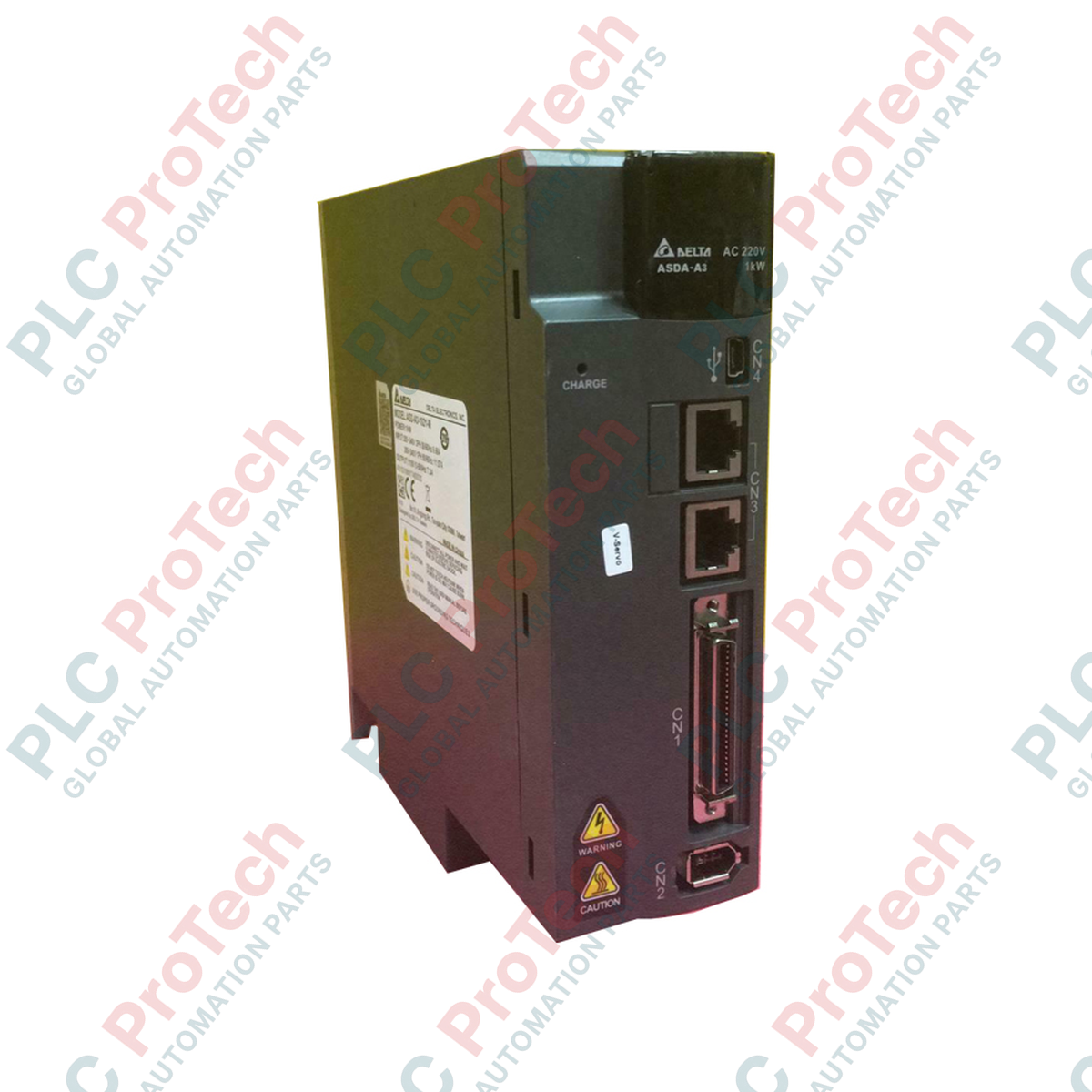
Engineered for high-dynamic response and precise motion control, the Delta Electronics ASD-A3-2023-F coordinates advanced multi-axis automation schemes as a core component of the high-performance ASDA-A3 Series AC servo system. Operating on a three-phase 220 VAC supply, this drive delivers high-bandwidth servo loops, boasting a 24-bit encoder resolution (16,777,216 pulses per revolution) to ensure maximum positioning accuracy and smooth low-speed performance.
The drive integrates sophisticated hardware filter algorithms that actively suppress mechanical resonance and structural vibration, safeguarding critical system components. Equipped with a built-in regenerative resistor and a flexible tuning interface, it adapts seamlessly to complex motion profiles in heavy industrial environments.
Features
-
Advanced SVPWM Control: Implements optimized Space Vector Pulse Width Modulation to maximize torque output and efficiency while minimizing thermal accumulation.
-
24-bit High-Resolution Feedback: Supports fine-grain positioning command tracking and stable velocity regulation even under low-speed operations.
-
Dual-Layer Resonance Suppression: Features low-pass and P-curve filtering strategies to isolate and dampen structural micro-vibrations automatically.
-
Integrated Regenerative Circuit: Features an onboard regenerative resistor to manage energy dissipation during decelerating phases.
-
Dynamic Tuning Options: Offers both automated auto-tuning algorithms for rapid commissioning and manual parameter tuning for specialized applications.
Applications
- High-speed packaging, sealing, and labeling machinery.
- Multi-axis CNC machining centers and precision gantry positioning systems.
- Automated pick-and-place electronic assembly and semiconductor processing lines.
- Industrial robotic articulation and material handling systems.
Technical Specifications
| Technical Parameter |
Specification Details |
| Manufacturer |
Delta Electronics |
| Model Number |
ASD-A3-2023-F |
| Product Series |
ASDA-A3 |
| Power Rating |
2.0 kW |
| Main Circuit Input Phase/Voltage |
Three-phase 200 VAC to 230 VAC |
| Permissible Voltage Range |
Three-phase 170 VAC to 253 VAC (-15% to +10%) |
| Rated Input Current (3PH) |
13.36 A |
| Encoder Resolution |
24-bit (16,777,216 pulses per revolution) |
| Control Method |
SVPWM Control |
| Speed Control Range |
1:6000 |
| Regenerative Resistor |
Built-in (Internal) |
| Cooling System |
Forced-air fan cooling |
| Dimensions (W x H x D) |
95 mm x 180 mm x 200 mm |
| Net Weight |
2.7 kg |
| Shipping Weight (Calculated) |
4.0 kg |
Empirical Engineering Insights
Alternative Models & Compatibility
The ASD-A3-2023-F is a direct technological upgrade to the older ASDA-A2 series (such as ASD-A2-2023-F). While mounting foot patterns remain structurally compatible, please note that the A3 series utilizes a 24-bit absolute encoder interface. Consequently, older 20-bit incremental ECMA motors cannot be paired with this drive unless specific signal conversion blocks are introduced. Always ensure compatibility with the ECMA-series high-resolution motors during field migration.
Application Pitfalls & Engineering Notes
Under severe regenerative conditions (e.g., highly vertical movements or high-inertia start-stop loads with cycles exceeding a 10% duty factor), the built-in regenerative resistor may experience thermal overload, triggering an AL005 (Overvoltage) fault. To bypass this failure point, remove the internal jumper wire across the P and D terminals and wire an external power resistor to the P and C terminals while configuring parameter P1-52 to match the new resistance rating.
Commissioning & Wiring Tips
Always execute 360-degree shielding termination on the encoder feedback line directly at the drive ground clamp to prevent high-frequency EMI leakage from the adjacent motor power phase lines. When commissioning via Delta's ASDA-Soft utility software, execute the inertia calculation under a restricted, low-velocity cycle first before activating the auto-tuning function, allowing the auto-notch filters to characterize structural resonances accurately.
Installation Guidelines
CRITICAL WARNING: HAZARD OF ELECTRICAL SHOCK, EXPLOSION, OR ARC FLASH. Turn off all power supplying this equipment before working on it. After disconnecting input power, wait a minimum of 10 minutes to allow the internal DC bus capacitors to discharge down to a safe level (less than 36 VDC) before touching any internal terminals or connection pads.
1
Mount the servo drive vertically on an unpainted, conductive panel inside an IP54-rated metal enclosure. Maintain at least 10 mm of clear lateral space and 50 mm of vertical space above and below the cooling fan vents.
2
Connect the protective earth (PE) terminal to the main system ground point first using a heavy gauge copper conductor to minimize electrical noise loops.
3
Terminate the three-phase AC input supply (200 VAC to 230 VAC) at terminals L1, L2, and L3. Ensure correct branch circuit protection fuses are sized according to rated inputs.
4
Wire the motor power cable to terminals U, V, and W, and plug the encoder feedback connector into the CN2 port. Avoid laying power cables and feedback cables in the same conduit.