Description
Designed to execute synchronized multi-axis control within a single space-saving envelope, the Mitsubishi Electric MR-J4W2-44B is a dual-axis digital AC servo amplifier operating on the MELSERVO-J4 platform. By consolidating control electronics for two independent 0.4 kW axes, this unit significantly reduces control panel footprints, optimizes power distribution, and streamlines network routing. The integration of high-speed SSCNET III/H optical fiber communications enables high-resolution motion synchronization with negligible electromagnetic interference, making it an ideal choice for high-speed, multi-axis automated assemblies.
Features
-
Dual-Axis Integration: Drives two independent rotary or linear servo motors up to 0.4 kW each, cutting cabinet space requirements by up to 30 percent.
-
SSCNET III/H Protocol: High-speed optical bus operating at 150 Mbps for precise, deterministic synchronized control with complete noise immunity.
-
Advanced Vibration Suppression Control II: Dynamically compensates for mechanical resonance in both high-frequency structural elements and low-frequency load oscillation.
-
One-Touch Tuning: Real-time estimation of mechanical inertia ratio enables instantaneous auto-tuning of servo gains.
-
Functional Safety Support: Integrated Safe Torque Off (STO) functions compliant with international safety standards.
Applications
- Synchronized multi-axis packaging machinery and cartoning lines.
- High-speed pick-and-place gantry robots and semiconductor assembly systems.
- Precise X-Y positioning tables and material handling conveyors.
- Automated winding, indexing, and labeling machinery.
Technical Specifications Table
| Manufacturer |
Mitsubishi Electric |
| Model Number |
MR-J4W2-44B |
| Series Name |
MELSERVO-J4 (MR-J4) |
| Controlled Axes |
2 Axes (Axis A and Axis B) |
| Rated Output Power |
0.4 kW per axis (Total 0.8 kW) |
| Communication Interface |
SSCNET III/H (Optical connection) |
| Main Circuit Power Supply |
3-phase 200 to 240 VAC, 50/60 Hz |
| Control Circuit Power Supply |
1-phase 200 to 240 VAC, 50/60 Hz |
| Encoder Compatibility |
22-bit absolute/incremental systems |
| Cooling Method |
Natural cooling |
| Ambient Operating Temperature |
0 to 55 degC (non-freezing) |
| Dimensions (H x W x D) |
195 mm x 60 mm x 168 mm |
| Net Weight |
1.4 kg |
| Shipping Weight (Calculated) |
3.5 kg |
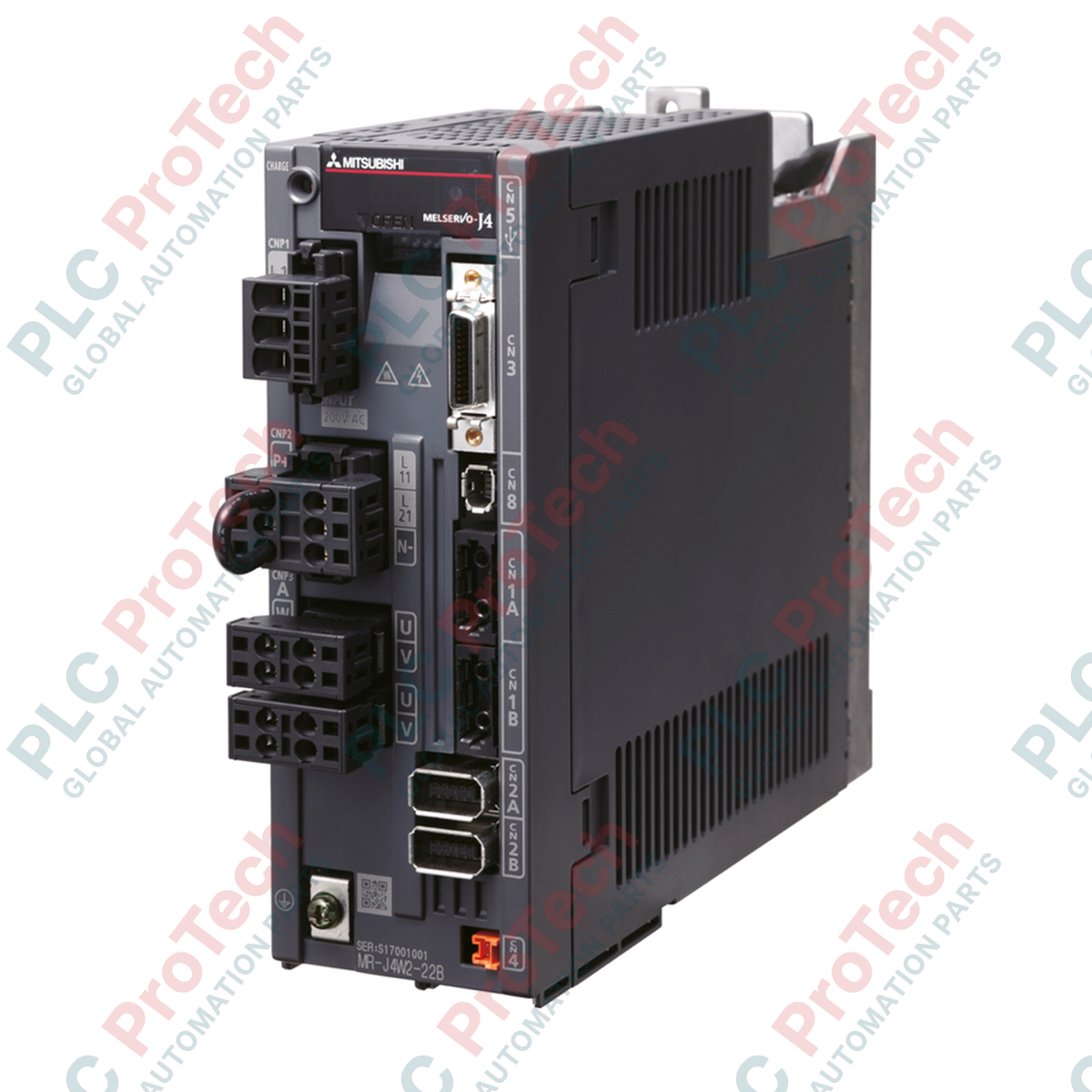
Connections and Interfaces
| Terminal / Connector Code |
Functional Assignment |
| L1 / L2 / L3 |
Main circuit power supply input (200-240 VAC) |
| L11 / L21 |
Control circuit power supply input |
| U / V / W (Axis A) |
Servo motor output terminals for Axis A |
| U / V / W (Axis B) |
Servo motor output terminals for Axis B |
| CN1A / CN1B |
SSCNET III/H optical fiber loop connectors (In/Out) |
| CN2A / CN2B |
Encoder connection interfaces for Axis A / Axis B |
| CN8 |
Functional safety signal connector (STO) |
Alternative Models & Compatibility
The MR-J4W2 series is designed as the primary platform for multi-axis configurations within the MR-J4 ecosystem. Note that when migrating legacy MR-J3W units to the MR-J4W2 configuration, parameter translation within the programming suite (such as GX Works2 or GX Works3) is required. While physical mounting footprints differ slightly from single-axis units, the space gains from eliminating independent control power cabling easily justify the transition.
Application Pitfalls & Engineering Notes
Because both Axis A and Axis B share a common internal DC bus, regenerative energy from decelerating one axis is naturally utilized by the second motoring axis. However, if both axes undergo simultaneous high-inertia deceleration, the regenerative capacity can quickly saturate the internal capacitor, triggering an Overvoltage (AL.33) fault. For operations with continuous regenerative cycles or high load inertia, always calculate total system regeneration requirements and connect an appropriately sized external regeneration resistor across the L+ and L- terminals.
Commissioning & Wiring Tips
When laying the SSCNET III/H optical fiber cables (MR-J3BUS_M), do not violate the minimum bend radius of 25 mm. Sharp bends or excessive zip-tie tension on the fiber optic routing will attenuate the light signal, leading to random line failures (AL.37) or communication errors (AL.E6). Always cap unused optical ports on the amplifier to prevent dust and humidity contamination of the optical transceiver lens.
Installation Guidelines
CRITICAL WARNING:
Risk of electric shock and residual charge discharge. Always disconnect the main circuit and control circuit power supplies before beginning physical installation or wiring. Wait at least 15 minutes after power-down for the internal charge lamps on the front face of the amplifier to completely extinguish before handling cable connections.
1
Mount the servo amplifier vertically on a flat, unpainted metallic surface to guarantee low impedance grounding and maximize thermal heat transfer.
2
Ensure a clear spacing of at least 40 mm above and below the housing, and at least 10 mm on either side of the chassis to allow unobstructed airflow.
3
Connect the protective earth (PE) terminal to the cabinet grounding panel before connecting any input power phases or encoder cables.