Description
Providing high-density current control capabilities within industrial automation architectures, the Omron CJ1W-DA08C coordinates precise loop regulation for up to eight independent field actuators. This Special I/O Unit interfaces directly with the host controller CPU via the high-speed CJ system bus, converting digital command values into stable 4 to 20 mA analog control loops. Engineered for demanding process environments, it features robust electrical isolation between the internal logic circuitry and external field wiring terminals, minimizing noise susceptibility and safeguarding backplane integrity. The module is completely configurable through the PLC memory map, eliminating the need for manual potentiometer adjustments.
Features
-
High-Density Control: Houses 8 independent current-loop analog outputs in a compact single-slot width.
-
Standard Signal Range: Supports industrial standard 4 to 20 mA analog output signals for broad actuator compatibility.
-
High-Resolution Conversion: Delivers 12-bit digital-to-analog conversion resolution (1/4000 scale) for tight process control tolerances.
-
Hot-Swappable Terminal Block: Uses a removable screw-terminal block to permit fast module replacement without disturbing field wiring.
-
Unified Configuration: All output scaling, limit, and status registers are integrated directly into the CPU's Special I/O Unit memory allocations.
Applications
- Proportional control valve positioning in fluid and gas processing systems.
- Variable frequency drive speed referencing and motor ramp control.
- Analog input reference signaling for distributed remote terminal units (RTUs).
- Retransmission of process variables to local paperless recorders and panel meters.
Technical Specifications Table
| Parameter |
Specification Value |
| Manufacturer |
Omron |
| Model Code |
CJ1W-DA08C |
| Unit Type |
Special I/O Unit |
| I/O System Connection |
CJ I/O Bus |
| Analog Output Channels |
8 |
| Output Signal Range |
4 to 20 mA |
| D/A Resolution |
12-bit (1/4000) |
| Terminal Connection Type |
Removable Screw Terminals |
| Country of Origin |
Japan |
| Shipping Weight (Calculated) |
1.5 kg |
| Package Dimensions (Calculated) |
89 mm x 31 mm x 90 mm |
Empirical Engineering Insights
Alternative Models & Compatibility
When migrating control schemes or performing drop-in replacements, ensure that your existing output loop utilizes 4 to 20 mA current and not voltage. If your system requires a voltage reference, choose the CJ1W-DA08V (0 to 10V / -10 to +10V) model instead. For smaller architectures, the 4-channel CJ1W-DA041 presents a lower-density footprint sharing the same software programming structure.
Application Pitfalls & Engineering Notes
An external 24 VDC power supply must be connected to the module terminal block to drive the internal digital-to-analog converter and current-loop output circuits. If this external supply drops below 20.4 VDC, output channels will clamp or lose calibration accuracy. To prevent high thermal buildup inside small enclosures when driving all 8 outputs at 20 mA simultaneously, ensure adequate vertical air clearance around the PLC rack assembly.
Commissioning & Wiring Tips
Unused output channels must be explicitly disabled in the PLC's Special I/O Unit parameter setup (DM Area). Leaving unused outputs enabled can lead to system CPU scan delays and trigger diagnostic errors. Always route the 4 to 20 mA field lines using shielded twisted-pair (STP) cabling, grounding the shield strictly at the PLC side to mitigate common-mode electrical noise.
Installation Guidelines
CRITICAL WARNING
Disconnect all primary power sources supplying the PLC backplane and external loop instrumentation before mounting, removing, or wiring this module. Failure to fully de-energize the assembly can cause unexpected actuator activation, system component damage, or communication failure across the SYSMAC bus.
1
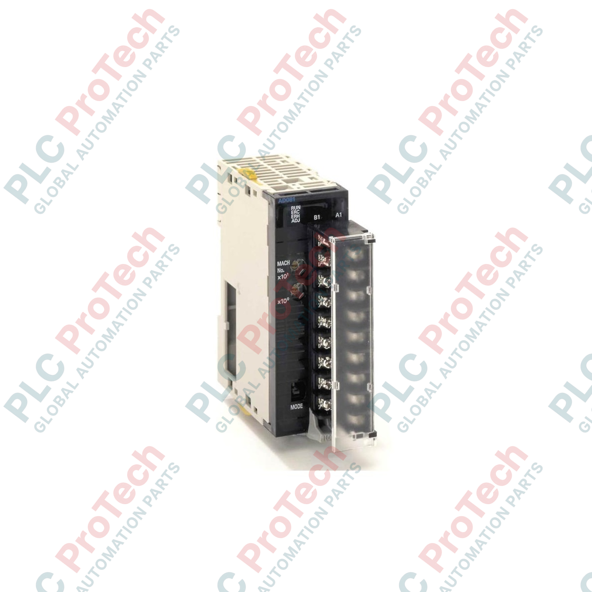
Set the unit number rotary switches located on the front face of the module to match your system software allocation settings. Ensure no duplicate unit numbers exist on the same rack.
2
Align the module's top and bottom positioning catches with the backplane guides, then pivot the unit firmly into place until the locking latches click.
3
Connect the external 24 VDC auxiliary loop power supply wires to the designated power inputs on the terminal block.
4
Terminate the shielded twisted-pair cables for each loop output channel, double-checking correct polarities (+/-) on the screw terminals.