Description
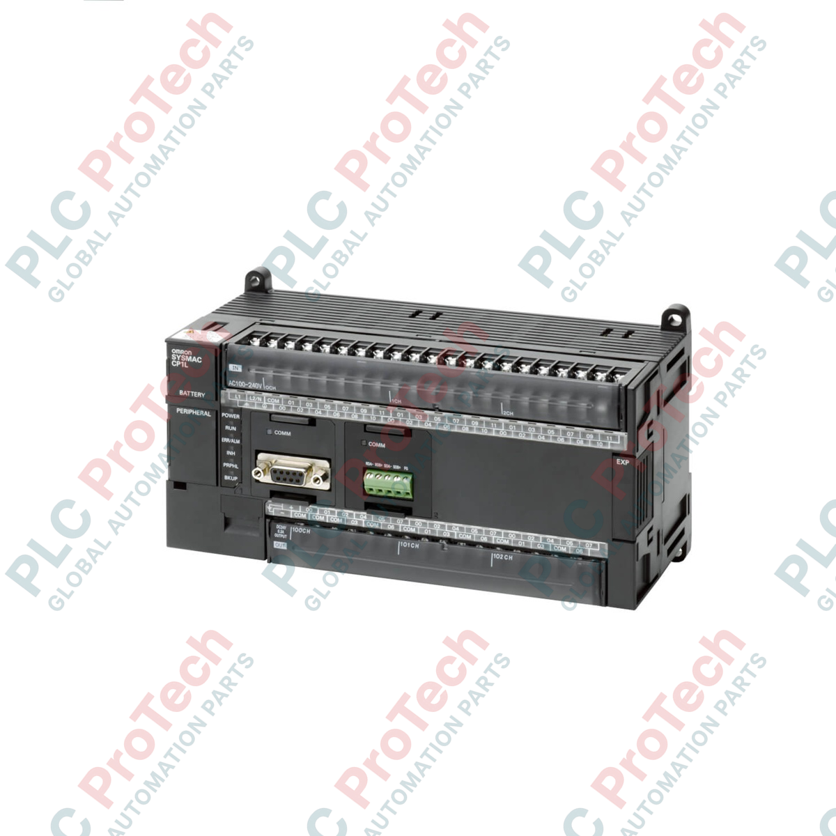
Engineered to deliver fast processing and reliable machine control, the Omron CP1L-M60DT-A serves as a robust central processing unit within the CP-series micro-PLC architecture. This controller integrates 36 inputs and 24 sinking transistor outputs into a single space-saving chassis, powered by an industrial-grade 100 to 240 VAC supply. Built with 10K steps of program memory and dedicated high-speed counters, it is optimized for small to medium-scale manufacturing applications requiring precise positioning, high-speed signal tracking, and multi-axis synchronization.
Product Features
-
Comprehensive Built-In I/O: Outfitted with 60 physical I/O points (36 digital inputs and 24 sinking transistor outputs) for versatile field device integration.
-
Multi-Axis Positioning: Built-in pulse outputs supporting 2 axes at 100 kHz, alongside 4 axes of 100 kHz high-speed counter inputs.
-
Expandable Architecture: Connect up to 3 CP-series expansion or expansion I/O modules, enabling scalable configurations up to 180 total I/O points.
-
Flexible Programming: Supports complex ladder logic, structured text (ST), and up to 128 functional block definitions for structured code management.
-
Dual-Layer Memory Backup: Preserves critical logic and parameter states using internal Flash memory and physical battery backup.
Applications
- Packaging machinery and automated labeling stations.
- Multi-axis pick-and-place coordinate tables.
- Conveyor control, sorting systems, and material handling lines.
- Custom assembly tooling and dedicated test benches.
Technical Specifications
| Parameter |
Specification |
| Manufacturer |
Omron |
| Model Number |
CP1L-M60DT-A |
| Series |
CP1L Series |
| Supply Voltage |
100 to 240 VAC (50/60 Hz) |
| Built-in Inputs |
36 Inputs (24 VDC) |
| Built-in Outputs |
24 Outputs (Transistor, Sinking/NPN) |
| Program Capacity |
10K steps |
| Data Memory Capacity |
32K words (DM Area) |
| High-Speed Counters |
4 axes, 100 kHz |
| Pulse Outputs |
2 axes, 100 kHz |
| Basic Instruction Execution Time |
0.55 microseconds min. |
| Backup Battery Life |
5 years at 25 degC |
| Shipping Weight (Calculated) |
3.0 kg |
| Package Dimensions (Calculated) |
160 x 140 x 110 mm |
Empirical Engineering Insights
Alternative Models & Compatibility
The CP1L-M60DT-A can replace legacy CPM2A-60CDT-D or similar system configurations with minor program modifications using CX-Programmer. When upgrading, note that the CP1L platform uses a CP-series expansion scheme. Ensure address maps are cross-referenced, particularly when shifting from CPM-style memory block allocations to the CP1L structure.
Application Pitfalls & Engineering Notes
This model employs sinking (NPN) transistor outputs. Wiring common pins to positive terminal potentials instead of standard negative configurations will prevent proper output switching and can cause physical damage to the internal optocouplers. Keep current draw below the rated threshold per terminal group to avoid thermal stress under intensive continuous cycling.
Commissioning & Wiring Tips
When utilizing the high-speed counter inputs for encoder feedback, run high-speed signal wires in a separate, shielded cable. Ground the shield at the PLC-side functional ground (FG) terminal only. This configuration protects the 100 kHz pulse inputs from high-frequency electromagnetic interference generated by adjacent variable frequency drives (VFDs).
Installation Guidelines
CRITICAL WARNING: Prior to mounting or performing wiring tasks on this controller, disconnect all primary AC power inputs (100-240 VAC). Allow at least 5 minutes for the internal energy storage capacitors to discharge to a safe level to avoid electrical shock or catastrophic equipment damage.
1
Securely mount the PLC onto a clean, grounded 35mm DIN rail inside a climate-controlled industrial panel matching at least IP54 specifications.
2
Connect L1 and L2 AC input supply lines through a dedicated circuit protection device, routing physical functional ground straight to system ground.
3
Wire field input sensors and output load common connections accurately, making sure not to cross sinking/sourcing signal polarities.