Description
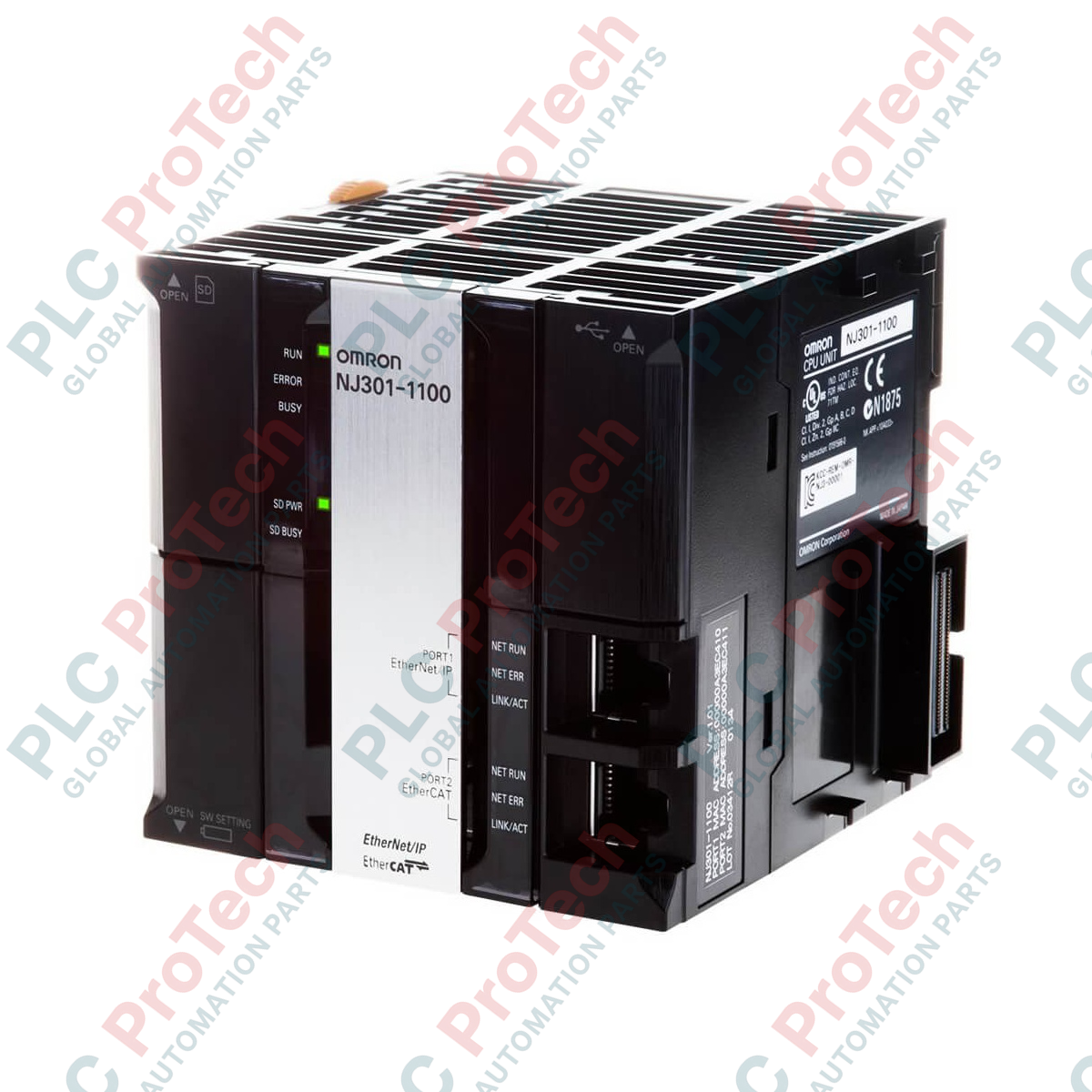
Integrating high-speed motion and sequence control into a unified database engine, the Omron NJ301-1100 serves as a high-performance central processing unit within the Sysmac NJ automation platform. This controller is designed to manage up to 4 synchronized axes and up to 15 total axes (including virtual), making it highly suitable for compact to mid-sized machine automation projects. Operating with a rapid 0.5 ms primary task cycle time and featuring 2.5 MB of variables memory, the unit ensures responsive, deterministic execution of complex logic and motion profiles. Standard built-in communication interfaces include EtherCAT Master, EtherNet/IP, and USB, facilitating seamless vertical integration and robust field-level device communication.
Features
-
Unified Control Engine: Integrates logic, motion, and vision control into a single, synchronized processor.
-
Multi-Axis Management: Supports precise control of 4 synchronized physical axes and up to 15 total axes.
-
High-Speed Execution: Delivers a consistent, deterministic 0.5 ms primary task cycle time.
-
Flexible Expansion: Connects directly to CJ-series I/O modules via the built-in CJ I/O Bus, supporting up to 40 expansion units.
-
Robust Connectivity: Equipped with onboard EtherCAT and EtherNet/IP ports for synchronized device networks and enterprise-level factory integration.
Applications
- Primary packaging and cartoning systems requiring coordinated multi-axis motion.
- Pick-and-place assembly stations utilizing delta or SCARA robotics.
- Automated material handling, sorting systems, and conveyor line control.
- High-speed test stands requiring deterministic sensor-to-actuator latency.
Technical Specifications
| Parameter |
Specification |
| Manufacturer |
Omron |
| Model / SKU |
NJ301-1100 |
| Controller Series |
Sysmac NJ3 |
| Functional Capabilities |
Motion Control, Sequence Control |
| Synchronous Axes (Max) |
4 |
| Total Axes (Max, incl. Virtual) |
15 |
| Primary Task Cycle Time |
0.5 ms |
| Variables Memory Capacity |
2.5 MB |
| Onboard Communication Ports |
EtherCAT Master, EtherNet/IP, USB (Type-B) |
| Local Expansion Bus System |
CJ I/O Bus (Supports up to 40 expansion units) |
| Remote I/O Node Capacity |
Up to 192 nodes |
| Unit Dimensions (L x W x H) |
90 mm x 90 mm x 90 mm |
| Unit Weight |
530 g (0.53 kg) |
| Shipping Weight (Calculated) |
2.00 kg |
Connections and Interfaces
| Port / Interface |
Physical Connector |
Function / Assignment |
| EtherCAT Port |
RJ45 (Shielded) |
Real-time network master for servo drives, variable speed drives, and remote I/O terminal modules. |
| EtherNet/IP Port |
RJ45 (Shielded) |
Host communications, programming, HMIs, peer-to-peer PLC data exchange, and tag data link connections. |
| USB Port |
USB 2.0 Type-B |
Direct local connection point for Sysmac Studio engineering software. |
Empirical Engineering Insights
Alternative Models & Compatibility
The NJ301-1100 CPU integrates legacy CJ-series physical form factors while running the modern Sysmac NJ firmware architecture. Note that while CJ-series I/O modules are physically compatible and mount directly on the local bus, they must be registered in the Sysmac Studio configuration tool rather than legacy CX-Programmer. Programs developed for CJ1/CJ2 PLCs cannot be directly downloaded and must undergo conversion within Sysmac Studio before execution.
Application Pitfalls & Engineering Notes
When utilizing the CJ I/O Bus expansion units alongside high-density communication modules or high-current analog units, calculate the total current consumption across the internal 5 VDC and 24 VDC rails carefully. Ensure your chosen Power Supply Unit (PSU) can supply the calculated current. Also, maintain a minimum of 20 mm clearance above and below the rack assembly to permit adequate convective cooling; failures to provide sufficient thermal headroom can lead to localized heat buildup and memory corruption or watchdog errors.
Commissioning & Wiring Tips
Always use Category 5e (or better) Double-Shielded Twisted Pair (STP) cables for both EtherCAT and EtherNet/IP connections. To prevent ground-loop noise on the communication lines, ground the functional ground (FG) terminal of the power supply unit and CPU rack using a heavy-gauge conductor tied to a dedicated low-resistance grounding block (less than 100 ohms). Verify that the EtherCAT cable shields make complete, continuous contact with the RJ45 metallic shell connectors.
Installation Guidelines
CRITICAL WARNING
Disconnect all electrical supply sources before physically mounting, wiring, or swapping any components. Never insert or extract CJ-series I/O modules from the system bus while the CPU is powered on. Failure to comply can damage the internal bus drivers of both the CPU and adjacent expansion modules.
1
Mount the CPU unit and adjacent power supply module firmly to standard 35 mm DIN rail or directly to the backplane panel using the integrated mounting brackets.
2
Slide the side connectors together until the locks click into place, securing the CPU module to the power supply unit on its left and any CJ-series modules on its right.
3
Terminate the industrial communication network cables in their dedicated RJ45 ports (EtherCAT and EtherNet/IP), ensuring appropriate strain relief and shielding configurations.
4
Connect the main functional ground to the dedicated rack ground lug, then apply primary supply voltage and verify successful boot sequences via the LED diagnostics on the front faceplate.