Description
Facilitating high-integrity safety network integration, the Triconex 3411 serves as the primary communications gateway for Tricon triple-modular redundant (TMR) safety systems. This Tricon Communication Module (TCM) enables secure, high-bandwidth communication between the safety controller and external networks, distributed control systems (DCS), or human-machine interfaces (HMI). Engineered for maximum fault tolerance, the Triconex 3411 isolates the critical safety core from external network disturbances, ensuring that communication processes do not compromise safety-critical execution. With support for dual-port configurations and industry-standard industrial protocols, it delivers continuous, real-time diagnostic reporting and process data visualization.
Features
- Provides physical and logical separation between safety-critical control and open networks.
- Supports concurrent communication over multiple protocols including Modbus TCP, Modbus RTU, TriStation, and TSAA.
- Designed for online hot-swapping, allowing module replacement without system shutdown or process interruption.
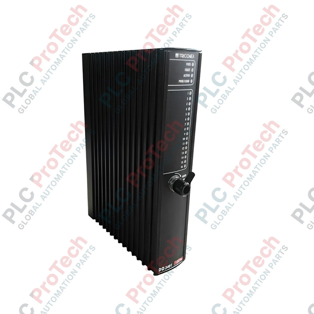
- Equipped with front-panel LED indicators indicating active communication, TX/RX activity, and system health status.
- Built-in hardware diagnostics constantly verify network interface integrity and signal quality.
Applications
- Emergency Shutdown Systems (ESD)
- Burner Management Systems (BMS)
- Fire and Gas Detection Systems (F&G)
- High-Integrity Pressure Protection Systems (HIPPS)
- Turbomachinery Control and Protection
Technical Specifications Table
| Parameter |
Specification |
| Manufacturer |
Triconex (Schneider Electric) |
| Model Number |
3411 |
| Module Type |
Tricon Communication Module (TCM) |
| System Compatibility |
Tricon v10 and v11 Safety Systems |
| Communication Protocols |
Modbus TCP/IP, Modbus RTU, TriStation, TSAA, Ethernet/IP |
| Maximum Data Rate |
100 Mbps |
| Interface Ports |
2 x RJ45 (Copper Ethernet), 1 x Fiber Optic (Multimode) |
| Power Requirements |
24 VDC (Nominal), plus or minus 10% |
| Operating Temperature |
-10 to 60 degC |
| Country of Origin |
United States |
| Shipping Weight (Calculated) |
3.5 kg |
| Package Dimensions (Calculated) |
6.2cm x 42.0cm x 17.7cm |
Connections and Interfaces
| Connector / Interface |
Function / Circuit Assignment |
| NET 1 (RJ45 / Fiber) |
Primary Ethernet port for TriStation diagnostic or Peer-to-Peer controller links. |
| NET 2 (RJ45 / Fiber) |
Secondary Ethernet network interface. Can be configured for independent TCP/IP segments. |
| Serial Connector |
RS485/RS232 connection for local Modbus RTU serial configurations. |
Alternative Models & Compatibility
The Triconex 3411 replaces older communication profiles (such as legacy 3401 units). When retrofitting older systems, verify that the TriStation 1131 software configuration is updated with the correct hardware allocation map. The controller's Main Processors (MP) must be operating on a compatible firmware version (typically v10.4 or higher) to permit simultaneous module communications.
Application Pitfalls & Engineering Notes
Excessive, unmanaged network broadcast traffic can cause packet congestion on safety communication channels. To prevent watchdog timeouts, connect the 3411 interfaces through managed switches configured with IGMP snooping and multicast rate limiting. Avoid assigning both NET 1 and NET 2 ports to the same logical IP subnet without strict router routing configuration, as this can cause internal address resolution protocol collisions.
Commissioning & Wiring Tips
Ensure that fiber optic terminations are cleaned using lint-free, specialized communication wipes prior to insertion. For serial Modbus connections, verify that terminal-end 120-Ohm resistors are securely installed to prevent signal reflection. Standard shielded twisted pair (STP) Category 6 cabling is required for copper connections to ensure maximum electromagnetic noise immunity in high-voltage industrial enclosures.
Installation Guidelines
CRITICAL WARNING: De-energize all power distribution blocks leading to the module chassis backplane before conducting any installation or removal activities. Do not touch backplane gold fingers with bare hands. Static discharge can destroy CMOS processor elements. Wear a properly grounded ESD wrist strap throughout the installation procedure.
1
Inspect the Triconex 3411 module physical alignment keys and backplane pins for transit damage.
2
Slide the module carefully into the designated slot on the Tricon main or expansion chassis until the top and bottom ejector levers fully engage the metal frame.
3
Press both latch handles inward simultaneously to lock the module backplane connections securely into place. Tighten the hand retention screws.
4
Attach communications media (RJ45, fiber optic, or serial terminal plugs) and check diagnostic LED indicators during the boot sequence to verify correct initialization.