1 of 3

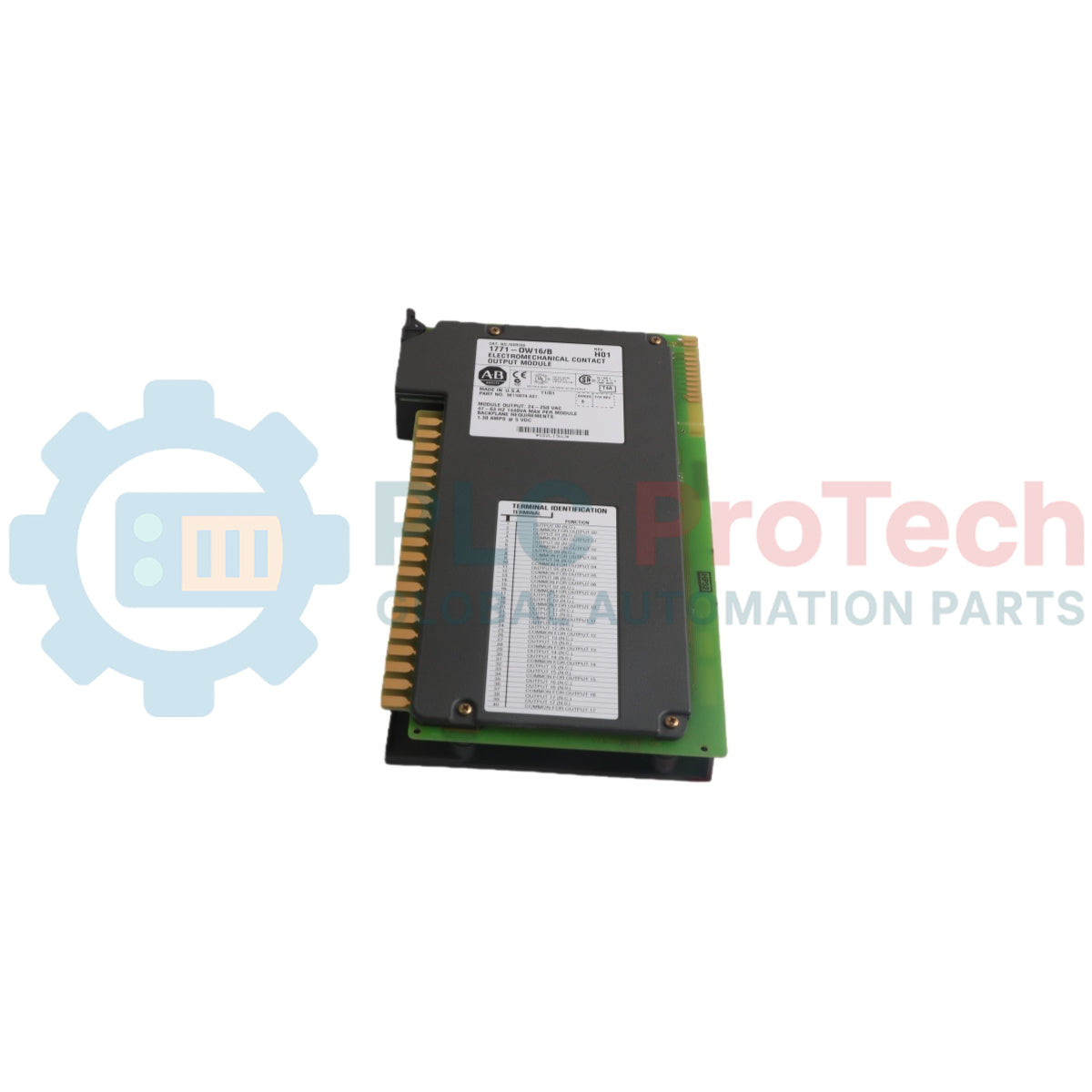
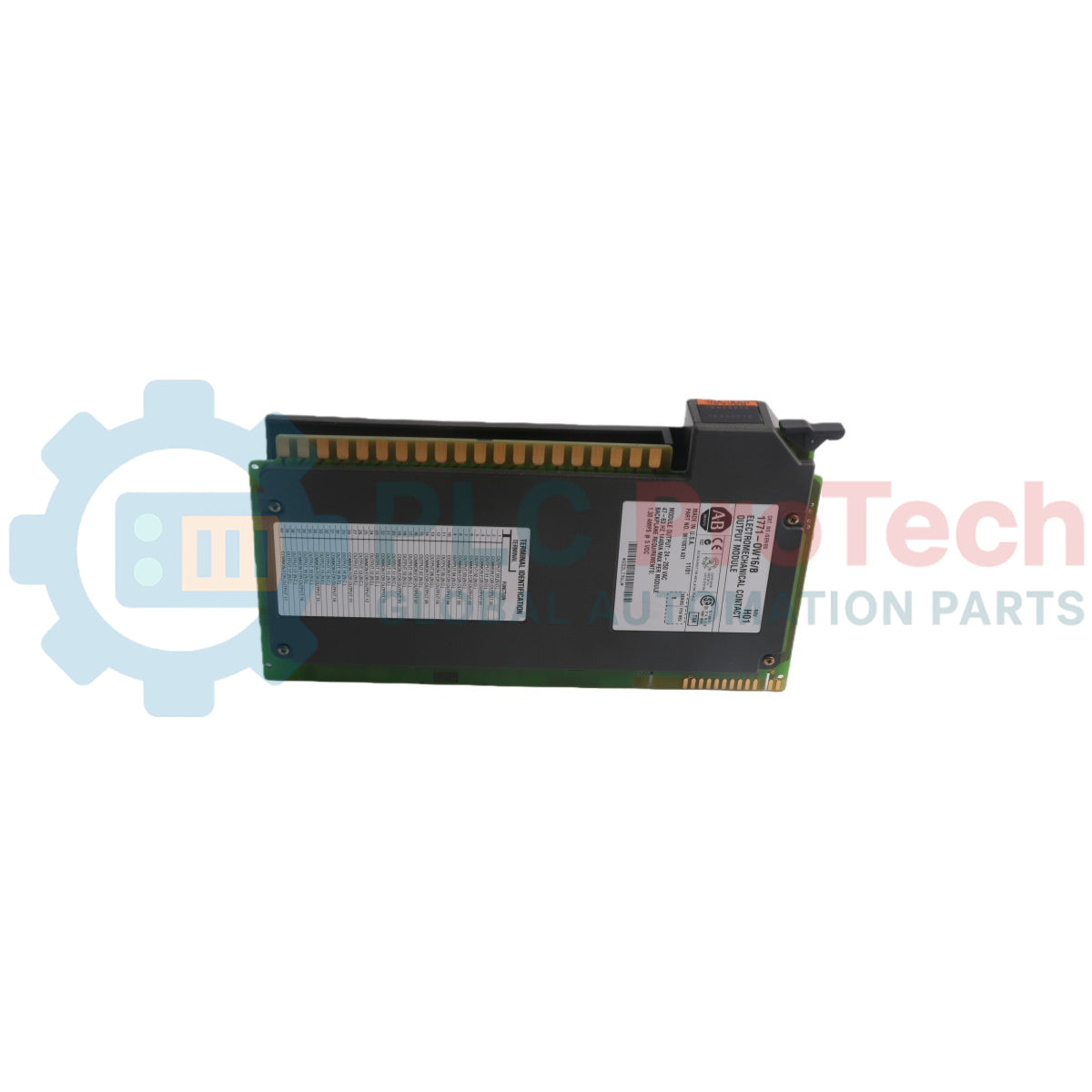
Allen-Bradley 1771-OW 1771 Selectable Contact Output Module

Allen-Bradley 1771-OW 1771 Selectable Contact Output Module

Only 7 item(s) left in stock
  • Manufacturer: Allen-Bradley

  • Product No.: 1771-OW

  • Country of origin:United States

  • Product Type: Selectable Contact Output Module

  • Barcode: 8537101190

  • Payment: T/T, Western Union

  • Weight: 520g

  • Dimensions: 315 mm x 45 mm x 145 mm (H x W x D)

  • Shipping port: Xiamen

  • Warranty: 12 months

Quantity
View full details

Description

The Allen-Bradley 1771-OW is a selectable contact output hardware module designed for integration within a 1771 I/O chassis. Functioning as a specialized switching unit, the device provides 8 outputs arranged into 4 isolated groups of 2, with each distinct group configured around its own independent common connection. Every individual output pathway is electrically isolated from the internal module logic circuitry, enabling the system to simultaneously drive separate external loads up to a maximum continuous current of 1.0A per output at rated power. Because the hardware does not contain built-in surge limiting circuitry, the 1771-OW must be utilized for switching resistive loads only, and it is not recommended for inductive or capacitive load setups. Logic control processing and internal relay coil energization paths are fully powered directly through the backplane of the host I/O chassis enclosure.

Features

  • Individually selectable output jumper configurations allowing each point to be customized for normally-open (N.O.) or normally-closed (N.C.) operation.
  • Four isolated circuit groupings containing two output lines per group to support multi-common wiring distribution.
  • Electrical isolation barriers separating field-side output contact switching loops from local backplane logic components.
  • Front-mounted diagnostic array consisting of 8 status indicators that illuminate when their corresponding output relay coils are energized.

Applications

  • Dedicated switching of resistive control loops in factory production environments.
  • Dry contact interface routing to external input modules or low-current logic devices.
  • Distributed automation control via multi-group contact isolation setups.

Technical Specifications

Parameter Specification
Manufacturer Allen-Bradley
Model Number 1771-OW
Product Line 1771 I/O
Product Type Selectable Contact Output Module
Outputs per Module 8 (4 groups of 2)
Module Location 1771 I/O chassis
Voltage Rating 24-138V ac RMS, 24-125V dc
Current Rating 1A per output (maximum)
Surge Current 1A maximum per output (at rated power)
Power Rating dc: 30W per output (resistive), ac (suppressed): 30W per output (resistive)
Minimum Contact Load dc: 10mA @ 24V, ac: 10mA @ 24V
Operate/Release Time 5ms maximum
Bounce Time 1ms maximum
Switching Frequency 10Hz maximum
Power Dissipation 3.7 Watts (max.): 3.3 Watts (min.)
Thermal Dissipation 12.6 BTU/hr (max.): 11.3 BTU/hr (min.)
Backplane Current 700mA maximum
Conductors 14 gauge stranded maximum
Wire Size 3/64 inch insulation maximum
Category 1
Operating Temperature 0 to 60 degC (32 to 140 Fahrenheit)
Storage Temperature -40 to 85 degC (-40 to 185 Fahrenheit)
Relative Humidity 5 to 95% (without condensation)
Field Wiring Arm 1771-WD
Wiring Arm Screw Torque 7-9 inch-pounds

Connections/Interfaces

Connector Pin Function
Output 0 Relay Contact Output 0 (Group 1)
Common Common Return Link for Outputs 0 and 1 (Group 1)
Output 1 Relay Contact Output 1 (Group 1)
Output 2 Relay Contact Output 2 (Group 2)
Common Common Return Link for Outputs 2 and 3 (Group 2)
Output 3 Relay Contact Output 3 (Group 2)
Output 4 Relay Contact Output 4 (Group 3)
Common Common Return Link for Outputs 4 and 5 (Group 3)
Output 5 Relay Contact Output 5 (Group 3)
Output 6 Relay Contact Output 6 (Group 4)
Common Common Return Link for Outputs 6 and 7 (Group 4)
Output 7 Relay Contact Output 7 (Group 4)

Installation Guidelines

  • Backplane Power Safety: Always remove full power from the 1771 I/O chassis backplane and the connected wiring arm before removing or installing any I/O hardware to avoid physical injury or unexpected system operation.
  • Electrostatic Discharge Protection: Prior to handling the physical circuit board assembly, touch a grounded object to discharge static buildup, and avoid touching the rear backplane connector pins.
  • Chassis Plastic Keying: Mount plastic keying bands onto the chassis backplane tracking points between positions 6 and 8, and between positions 16 and 18 to lock the chosen slot exclusively for this hardware type.
  • Module Placement Limits: The module can be installed in any available I/O chassis slot connector except for the leftmost slot position, which is strictly reserved for adapter or processor modules.
  • Jumper Configuration Control: To modify factory default normally-open operation, remove the 4 side screws to open the housing covers and manually transition internal jumpers K1, K2, K3, and K4 to their N.C. positions.
  • Interconnect Cable Length: Restrict total field wiring interconnect runs to a maximum boundary length of 1000 feet (304.8 meters).
  • Parallel Loading Warning: Do not hook up two or more outputs in parallel in an attempt to exceed the continuous 1A power rating, as minor deviations in individual relay response times can cause a single contact to bear the entire load current.

Product Documentation

Technical Datasheet (PDF) Complete specifications and technical drawings.

Technical Datasheet

Allen-Bradley 1771-OW 1771 Selectable Contact Output Module

What is the maximum allowed continuous current that can be applied across an individual output contact?

Each individual output can handle a maximum continuous load current of 1.0A at its rated power capacity.

Which specific catalog model of field wiring arm is required to attach field cables to the module?

Connections to the front panel points of the module must be made through the catalog number 1771-WD field wiring arm assembly.

What happens if a user connects multiple output lines in a parallel arrangement to handle a higher current load?

Paralleling outputs is strictly prohibited; slight variations in internal relay closing speeds can cause a single contact point to momentarily conduct the full load current, resulting in damage.

What are the exact backplane keying slots specified for installing the module inside the chassis?

The plastic keying bands must be positioned on the chassis backplane between positions 6 and 8, as well as between positions 16 and 18.

Global Express Shipping

  • Standard Delivery: 4-6 Business Days via DHL, FedEx, and UPS.
  • Express Dispatch: Same-day dispatch for in-stock orders placed before 2:00 PM (GMT+8).
  • Worldwide Coverage: Serving over 150 countries, including rapid delivery to Saudi Arabia and UAE.

Returns & Warranty

  • 30-Day Guarantee: Returns accepted for in-stock products in original, factory-sealed packaging.
  • 12-Month Warranty: Every industrial component is backed by our professional technical warranty.

Orders are processed and delivered Monday-Friday (excluding public holidays).


For full eligibility, restocking fees, and international return details, please view our official Refund & Return Policy .

TECHNICAL SPECIFICATIONS

Color pattern
Black
Country of origin
United States
Power source
DC Power

Recently Viewed Products

Technical knowledge

Modernizing Bailey INFI 90 Symphony HMIs Running on OpenVMS Alpha

A practical guide to replacing aging Bailey Symphony operator stations running on OpenVMS Alpha. It compares Alpha emulation, OpenVMS x86 migration, OPC re-platforming, and phased ABB modernization.

Why Maintenance Data Is Essential for Industrial Reliability

Maintenance data connects work orders, sensor signals, asset history, costs, and technician knowledge. Used well, it improves planning, reliability, predictive maintenance, spare-parts control, and...

Suyuqlik quvvat tizimlarini almashtirish uchun mo‘ljallangan elektr aktuatorlar: Amaliy sanoat avtomatizatsiyasi qo‘llanmasi

Ushbu maqola SMCning e-Actuator seriyasi kabi integratsiyalashgan elektr aktuatorlarining sanoat harakatini boshqarishda an’anaviy pnevmatik va gidravlik tizimlarni qanday almashtirayotganini...

Sanoat avtomatlashtirish ilovalari uchun OpenPLC yordamida matematik amallar bajarish

Ushbu maqola PLC tizimlari sanoat avtomatlashtirishida qo‘shish, ayirish, ko‘paytirish, bo‘lish, modulo va darajaga ko‘tarish kabi asosiy matematik amallarni qanday bajarishini tushuntiradi. Unda...

FBD PLC dasturlashda ilg‘or Boolean mantiqi: asosiy mantiqdan tashqari amaliy sanoat ilovalari

Maqola PLC dasturlashda asosiy AND, OR va NOT amallaridan tashqari bir nechta ilg‘or Boolean mantiq funksiyalarini tushuntiradi. Unda haqiqat jadvallari, multiplexerlar, impuls generatorlari va...

PLC dasturlashda Boolean mantiqi: FBD mantiq eshiklarini tushunish

Boolean mantiq har bir PLC dasturining asosidir. Oddiy mashina boshqaruvlaridan tortib murakkab sanoat avtomatlashtirish tizmlarigacha, mantiqiy eshiklar boshqaruvchilarning o‘zgaruvchan kirishlar va...