Общ преглед на системно ниво и експлоатационна стойност
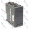
Модулът IC695PSA040 (IC695PSA040) е високоефективен 40-ватов захранващ модул, проектиран за платформата GE PACSystems RX3i. Работейки с универсални входни диапазони от 85 до 264 VAC или от 100 до 300 VDC, този модул осигурява стабилно разпределение на захранването директно по задната платка, за да захранва локалните процесорни модули и модулите за входове/изходи. Промишлените операции в автоматизирани пречиствателни станции за вода, предприятия за химическа преработка и производствени монтажни линии разчитат на IC695PSA040 (IC695PSA040) за осигуряване на предвидимо изпълнение на контролера при колебания в мрежовото захранване. Захранващият модул изолира вътрешната електроника на статива от електрически шум от полевата среда, регистрира прогнозни повреди директно в таблиците на централния процесор при термично или товарово натоварване и поддържа вградена функция за преходно захранване. Тази архитектурна устойчивост предотвратява внезапни отпадания на PLC, защитава критичните работни параметри и значително намалява скъпоструващите непланирани престои на производствените обекти.
Архитектурна инфраструктура и вътрешна защита
Хардуерната топология на модула IC695PSA040 е базирана на локализирано управление на изходите с три шини и автоматична електронна защита.
-
Изходно напрежение с три шини: Независимо подава +5.1 VDC и +3.3 VDC за нуждите на системните модули на RX3i, както и отделен изходен път +24 VDC за релета, предназначен за захранване на външни изходни релейни модули.
-
Активен контрол на свръхтока: Разполага с вградено електронно ограничаване на тока, което ограничава шината 5.1 VDC до 7 A, а шината 3.3 VDC до 10 A. При претоварване или късо съединение захранването се изключва автоматично и инициира непрекъснати опити за автоматично рестартиране, докато основната повреда на полевата верига не бъде отстранена.
-
Цялостна диагностика на състоянието: Разполага с масив от четири челни светодиодни индикатора за състоянието, свързани с вътрешни диагностични релета, които предават в реално време информация за прегряване, претоварване и състоянието на вътрешните компоненти директно към регистратора на повреди на централния процесор.
Данни за производителността и матрица на хардуера
| Инженерен индекс |
Техническа спецификация |
| Номер на модела |
IC695PSA040 |
| Идентификатор на марката |
GE PACSystems (General Electric) |
| Серия на системата за управление |
Контролери RX3i |
| Обща номинална изходна мощност |
Максимум 40 W общо |
| Номинални входни параметри |
120/240 VAC или 125 VDC |
| Диапазон на AC входа |
85 до 264 VAC |
| Диапазон на DC входа |
100 до 300 VDC |
| Максимална входна мощност |
Максимум 70 W при пълно натоварване |
| Праг на пусковия ток |
4 A за максимум 250 милисекунди |
| Спецификации на изходния ток |
5.1 VDC (0 до 6 A), 3.3 VDC (0 до 9 A), 24 VDC (0 до 1.6 A) |
| Граници на напрежението |
5.1 VDC (5.0 до 5.2 VDC), 3.3 VDC (3.1 до 3.5 VDC), 24 VDC (19.2 до 28.8 VDC) |
| Галванична изолация |
250 VAC непрекъснато (1500 VAC за 1 минута от входа към задната платка) |
| Продължителност на поддържане на захранването |
Минимум 20 ms при прекъсване на източника |
| Диапазон за полево окабеляване |
Единичен проводник от 14 AWG до 22 AWG на клема |
| Капацитет на последователно свързване |
До 4 модула PSA040 |
| Ограничения на работния въздух |
От 0 до 60 °C (външна околна температура) |
| Код за ATEX защита |
II 3 G Ex nA IIC T3C |
| Страна на произход |
Съединени щати |
Често задавани въпроси за техническа диагностика
Може ли захранващият блок IC695PSA040 да бъде конфигуриран в паралелна схема за постигане на резервираност N+1?
Не. Този конкретен захранващ блок е проектиран изключително за самостоятелна работа в универсална задна платка RX3i (каталожна серия IC695). Той не може да се комбинира с други захранващи блокове за увеличаване на системния капацитет или осигуряване на хардуерна резервираност. Опитът за работа на по-стари версии (IC695PSA040C и по-ранни) заедно с друг захранващ блок в същия слот на задната платка може да причини сериозна повреда на оборудването.
Какво причинява промяната на основния индикатор Power LED от постоянно зелено към жълто?
Зеленият светодиод показва, че модулът е включен и успешно подава стабилни постояннотокови захранващи напрежения към задната платка. Жълтият светодиод показва, че входното захранване е правилно подадено към входните клемни блокове на модула, но превключвателят на предния панел е в положение OFF, което предотвратява подаването на захранване към шкафа.
Какви основни системни неизправности причиняват пълно изключване, без да активират външен светодиоден индикатор за неизправност?
Във входната линия се намира вътрешна неподлежаща на ремонт стопяема връзка, която служи като последна хардуерна защита. Макар че модулът обикновено активира електронно изключване, преди този предпазител да откаже, силно вътрешно късо съединение на компонент или прекомерен входен импулс на пренапрежение може да прекъсне тази връзка завинаги. Когато предпазителят изгори, всички индикации за работа изчезват и модулът трябва да бъде физически заменен.
Протокол за сервизно инженерство и поддръжка на място
-
Мерки за предотвратяване на токов удар и безопасност при управление с превключвателя за включване/изключване:
По време на работа с източник на променлив ток по вътрешните електрически структури на модула има опасни напрежения (120 VAC или 240 VAC). Предната врата за достъп до клемите трябва да остава затворена при нормална работа, за да се предотврати опасност от смъртоносен токов удар. Имайте предвид, че предният превключвател ON/OFF зад вратата управлява само вторичните степени на постояннотоковия изход; той НЕ изключва входното мрежово захранване под напрежение от клемните блокове.
-
Поставяне на проводниците и ограничения на момента на затягане:
Оголете всички проводници на клемите на минимална дължина от 9 mm до 11 mm. Уверете се, че проводникът е поставен докрай в корпуса на клемата, докато изолацията му прилегне плътно към вътрешния ограничител на изолацията. Затегнете внимателно винтовите скоби, като се уверите, че не надвишавате максимално допустимия момент на затягане от 0.5 N-m (4.4 inch-lbs). Неправилното поставяне може да доведе до захващане на изолацията на проводника от винтовата скоба, което да причини прекъснати вериги или прегрели точки на свързване.
-
Джъмпер за защита от пренапрежение и процедура за Hi-Pot изпитване:
Долните клемни блокове съдържат защитна схема с варистор от метален оксид (MOV) срещу пренапрежение, която трябва да бъде свързана към заземяването на корпуса чрез монтиран от потребителя джъмпер за базова защита на входа от пренапрежение. За провеждане на диелектрично изпитване с високо напрежение (Hi-pot) на захранването трябва да деактивирате тази схема за защита от пренапрежение, като отстраните джъмпера. Монтирайте отново заземяващия джъмпер незабавно след приключване на изпитването, за да възстановите защитата от преходни пренапрежения.