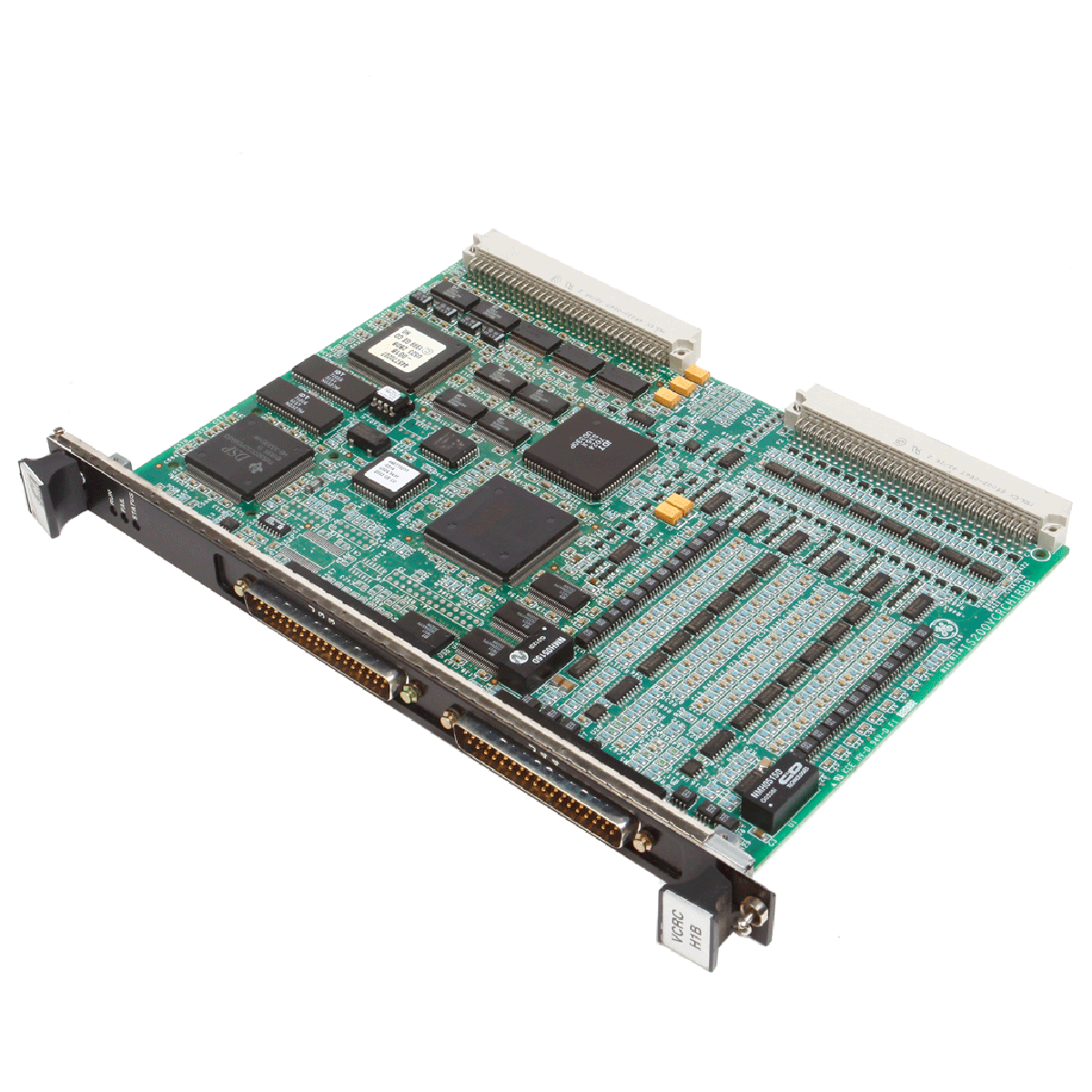
GE IS200JPDCG1A Mark VI Speedtronic платка за разпределение на захранването
В наличност
1 review
12-month warranty
Free returns within 30 days
Manufacturer:
General Electric
Country of origin:Съединени щати
Product Type:
Платка за електроразпределение
Payment:
T/T, Western Union
Weight:
2500g
Dimensions:
17.78(W) × 7.62(D) × 51.81(H) см
Shipping port:
Xiamen
Warranty:
12 months
Описание
IS200JPDCG1A функционира като наситена с компоненти платка за разпределение на захранването в системата за управление на турбини Mark VI на General Electric. Тя съчетава функции за разпределение на входове и изходи, за да подава 125 V DC, 115/230 V AC и 28 V DC към други клемни платки и пакети в системи за управление на парни, газови или вятърни турбини. IS200JPDCG1A служи като основен хост модул за I/O пакет за обратна връзка на системата за разпределение на захранването (PPDA), като директно прихваща и мултиплексира диагностични сигнали за обратна връзка от локални вериги и каскадно свързани разпределителни платки нагоре по веригата, за да улеснява мониторинга на системата чрез IONet.
Характеристики
Интегрирана поддръжка на обратната връзка PPDA: Помества I/O пакета PPDA върху конектора JA1 и маршрутизира локалните и каскадно свързаните диагностични сигнали, без да са необходими отделни линии за предаване на диагностични данни.
Разпределение на захранване по множество шини: Едновременно разпределя захранване 125 V DC, 115/230 V AC и 28 V DC в обособени зони на платката.
Обширна защита с полимерни предпазители: Включва двадесет и шест изхода, защитени с полимерни предпазители 1,6 A, за разпределение към спомагателни устройства, както и специални незапазени с предпазители силнотокови връзки за захранване на контролери и превключватели.
Каскадно свързване на платки нагоре по веригата: Оборудвана с 50-пинов конектор за плосък кабел (P2), поддържащ каскадното свързване на до четири допълнителни разпределителни платки към обратната връзка PPDA.
Възможност за отчитане на ток на утечка към земя: Разполага със схема за центриране на шината, активирана чрез джъмпера JP2, която свързва двете страни на шината 125 V DC към функционалната земя чрез резистори 84 kOhm за прецизен мониторинг на повреди.
Приложения
Системи за управление на газови и парни турбини
Приложения за управление на вятърни турбини за възобновяема енергия
Автоматизирани промишлени шкафове за управление, използващи инфраструктурата Mark VI Speedtronic
Информация за поръчка
Версия на модула
Подробности за конфигурацията
IS2020JPDCG01
Стандартна версия за повечето приложения за разпределение на захранването
IS2020JPDCG02
Специална версия с кабелен джъмпер върху диодния блок D1 за активиране на входа JD2 Battery B като изход
Технически спецификации
Артикул
Описание / Стойност
Производител
General Electric
Серия
Mark VI Speedtronic
Каталожен номер
IS200JPDCG1A
Функционално съкращение
JPDC
Входове 28 V DC (JR, JS, JT)
Макс. 19 A всеки, макс. 15 V
Изходи 28 V DC без предпазители (J1, JP1, JCR, JCS, JCT, JRS, JSS, JTS)
Макс. 13 A на щифт; общият ток не трябва да надвишава 12,5 A
Защитени с предпазители изходи 28 V DC (JR1-JR10, JS1-JS8, JT1-JT8)
Полимерен предпазител 1,6 A за всяка връзка
Вход 115/230 V AC (JAC)
Макс. 13 A, 115/230 V AC, 50/60 Hz (защита с автоматичен прекъсвач 30 A)
Изходи 115/230 V AC (JAC1, JAC2)
Макс. 10 A всеки, защитени с бавнодействащи предпазители 10 A, 250 V
Входове за 125 V DC батерия (JD1, JD2)
Общ ток макс. 20 A, диапазон на входното напрежение 90-145 V dc
Вход 125 V dc DACA (JZ2)
Макс. 10 A, номинално 125 V dc, максимално 145 V dc
Импеданс към земя
>75 kOhm (джъмперът JP1 е поставен), >1500 kOhm (джъмперът JP1 е отстранен)
Диапазон на работната температура
-30 до 65 degC (-22 до 149 по Фаренхайт)
Размери на платката
Ширина 17.2 cm x височина 48.26 cm (6.75 in x 19.0 in)
Размери на модула
Ширина 17.78 cm x височина 51.81 cm x дълбочина 7.62 cm (7.0 in x 20.4 in x 3 in)
Местоположение на завода
Салем, Вирджиния, САЩ
Връзки/Интерфейси
Конектор / Сигнал
Функция
JR, JS, JT
Входове за захранване 28 V dc
JAC
Вход за захранване 115/230 V ac
JAC1, JAC2
Изходи за захранване 115/230 V ac (JAC1 се превключва чрез SWAC1)
JD1, JD2
Входове за батерия 125 V dc (обединени чрез диодния модул D1)
JZ2
Свързване на модул DACA с 125 V dc
J1R, J1S, J1T
Изходи 125 V dc към външни захранвания dc/dc с 28 V dc
J7A, J7B, J7C
Изходи 125 V dc към клемните платки за релейни изходи TRLY
J8A, J8B, J8C
Изходи 125 V dc с ограничение на тока при късо съединение и последователни резистори 22 Ohm за платките TBCI
P2
50-щифтов конектор за плосък лентов кабел за входовете на диагностичната верига
JA1
62-щифтов D-shell конектор за пакета за обратна връзка на входовете/изходите PPDA
TB1
5-винтов клемен блок за конфигуриране на шинния съединител за 28 V dc
TB2, TB3, TB4
Достъпни директно клемни блокове за необработени аналогови диагностични сигнали за обратна връзка
Указания за монтаж
Ориентация при монтаж: Модулът трябва да бъде монтиран вертикално, като входният конектор за 115/230 V ac (JAC) се намира отдолу. Закрепете основата на модула към задната основа на панела с четири винта през предназначените за това горни и долни монтажни отвори.
Цялост на модула: За да предотвратите физическа повреда, не отстранявайте печатната платка от доставената от производителя стоманена монтажна плоча; винаги заменяйте платката и задната плоча като един цял модул.
Функционално заземяване (FE): Уверете се, че модулът е здраво закрепен към разположена под него ламаринена повърхност, заземена към мрежата за функционално заземяване (FE), за да се осигури правилна опорна точка за диагностичните вериги.
Защитно заземяване (PE): Отделни специално предназначени заземителни проводници трябва да свързват винтовите клеми E5 и/или E6 на модула директно към шината за защитно заземяване (PE) на корпуса. Заземителните пътища трябва да издържат 60 A за 60 секунди при пад на напрежение под 10 V.
Разполагане на филтрите: Поставете входните линейни филтри непосредствено върху PE-заземена основа или в непосредствена близост до PE шината на корпуса, като използвате минимална дължина на проводниците, за да ограничите радиочестотния импеданс.
Забавяне при повторно подаване на захранване: След като превключвателите SW1R, SW1S или SW1T бъдат поставени в положение OFF, изчакайте минимум 30 секунди, преди да подадете захранване отново, за да предотвратите повреда от разрушително пусково напрежение на свързаните входни вериги на захранванията с 28 V dc.
FAQ
Каква е целта на предупреждението за 30-секундно изчакване, обозначено върху превключвателите на модула?
Когато захранващите превключватели на външните DC/DC преобразуватели (SW1R, SW1S, SW1T) бъдат изключени, е необходимо да изчакате 30 секунди, преди да ги включите отново, за да предотвратите повреда от пусков ток на входните вериги на свързаните захранвания 28 V DC.
Как са разделени заземителните мрежи на платката за разпределение на захранването?
Платката разделя заземяването на връзка Protective Earth (PE) за безопасност на хардуера и пътищата през корпусите на превключвателите, и връзка Functional Earth (FE), използвана чрез монтажните опори като референтна точка за аналоговите сигнали за диагностична обратна връзка.
Защо няма вериги за диагностична обратна връзка за изходите за захранване J8A, J8B и J8C?
За тези конкретни изходи не са предвидени вериги за обратна връзка, тъй като захранват клемни платки за контактни входове (TBCI), които разполагат със собствени вградени схеми за вътрешен мониторинг на напрежението.
Как се нулира състояние на изключване с блокировка, причинено от събитие на свръхток на изходите за спомагателни устройства?
Двадесет и шестте спомагателни изхода са защитени с полифюзи 1,6 A, които се изключват с блокировка при условия на свръхток; за да ги нулирате, трябва да изключите и включите отново входното захранване на засегнатата верига с полифюз.
Стандартна доставка: 4-6 работни дни чрез DHL, FedEx и UPS.
Експресна изпращане: Изпращане в същия ден за налични поръчки, направени преди 14:00 ч. (GMT+8).
Глобално покритие: Обслужваме над 150 държави, включително бърза доставка до Саудитска Арабия и ОАЕ.
Връщания и гаранция
30-дневна гаранция: Връщания се приемат за налични продукти в оригинална, фабрично запечатана опаковка.
12-месечна гаранция: Всеки индустриален компонент е подкрепен с нашата професионална техническа гаранция.
Поръчките се обработват и доставят от понеделник до петък (с изключение на официалните празници).
За пълна информация относно допустимост, такси за презареждане и международни връщания, моля, разгледайте нашия официален
Политика за възстановяване и връщане
.
Преди да замените Yokogawa AAI835, проверете картата на каналите 4 входа/4 изхода, поведението на контура при отпадане на захранването, типа бариера, натоварването на изхода, кабела и резервирането.
Проверки при замяна на ABB TP853 3BSE018126R1: идентифицирайте инсталирания интерфейс CI853, CI855, CI857 или CI861, запишете окабеляването и проверете комуникацията след инсталирането.
Инженерни проверки за Allen-Bradley 5069-L330ERMS2: капацитет на контролера, отделни комплекти RTB, ограничения за локалните I/O, ограничения за мрежовите възли и брой оси за управление на движението.
Проверки, които трябва да се запишат преди подмяната на ABB 3HNE 00006-1 DSQC 351: поколение на контролера, окабеляване на X3/X5/X20/X21, настройки на DeviceNet, mapping на INTERBUS и състояния на...
Сравнете IC693CPU360 и IC693CPU364 по отношение на Ethernet интерфейса, консумацията от +5 VDC, паметта, ограниченията за шасито и проверките при замяна.
При задаване на избор се опреснява цялата страница.