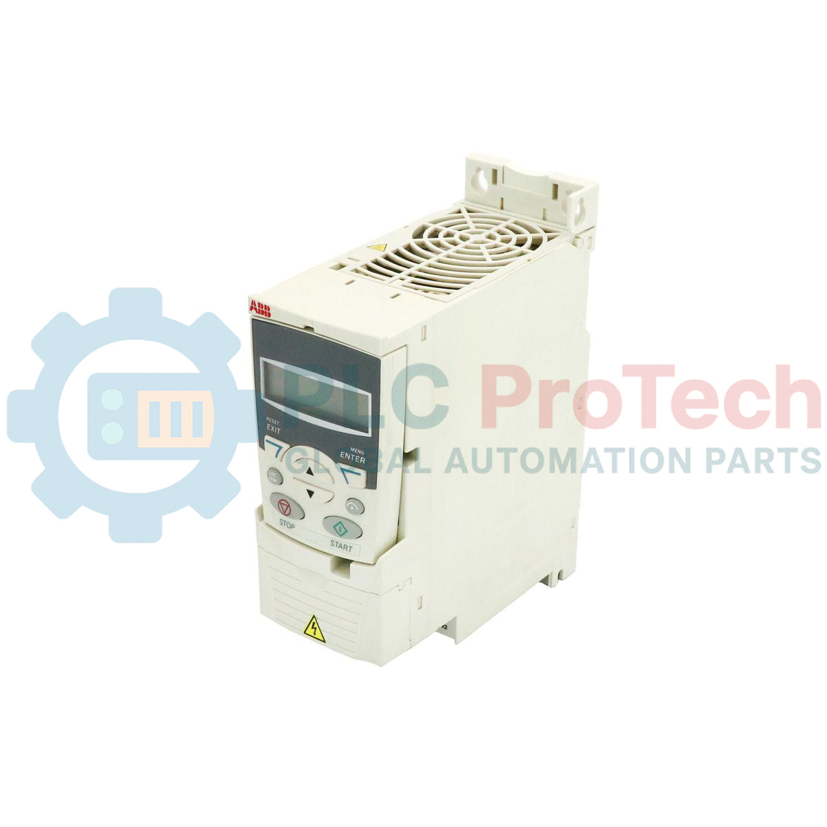
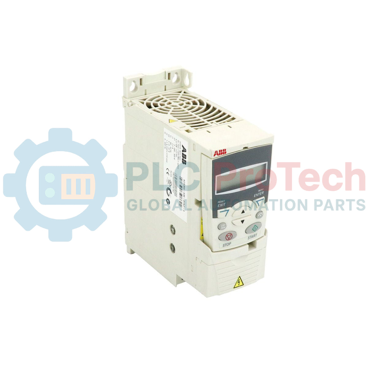
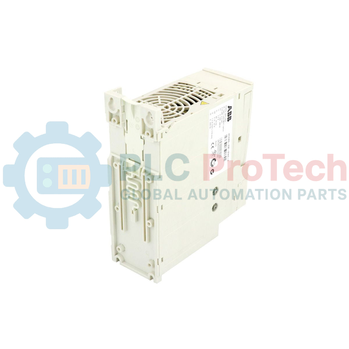
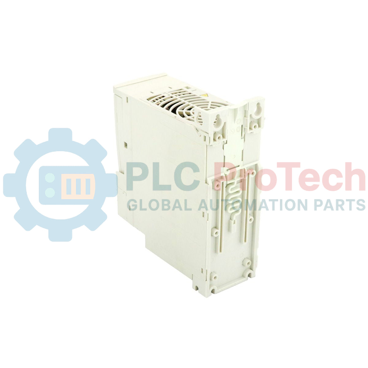
Description
Providing dynamic performance for low-power motor control, the ABB ACS355-03E-01A2-4 variable frequency drive integrates advanced scalar and vector control configurations for micro-drive installations. Engineered for rapid cabinet integration and OEM machine production, this three-phase 400V class AC drive offers exceptional precision in speed regulation, making it ideal for food and beverage, material handling, and textile processing applications. Equipped with an integrated Safe Torque Off (STO) terminal, it guarantees compliant functional safety (SIL3) directly out of the box without requiring external safety contactors.
Features
-
Flexible Motor Control: Supports both sensorless vector control (for induction and permanent magnet motors) and scalar control modes.
-
Integrated Functional Safety: Certified Safe Torque Off (STO) dual-channel interface complies with SIL3 and PL e safety standards.
-
Internal Braking Chopper: High-duty built-in brake chopper as standard, eliminating the need for external dynamic braking modules.
-
Compact R0 Frame Size: Unified height and depth footprints across the range allow optimized, side-by-side cabinet installation.
-
Sequence Programming: 8-state sequence programming engine enables independent control cycles without an external PLC.
-
EMC Filter: Integrated C3 class electromagnetic compatibility filter for standard industrial networks.
Applications
-
Conveyor Systems: Precise speed synchronization and high-starting torque for heavy friction loads.
-
Packaging Machinery: Rapid start/stop cycling with dynamic braking integration.
-
Pumps and Fans: Energy-efficient flow and pressure regulation with built-in PID controllers.
-
Mixers and Agitators: Constant torque profiles with robust overload protection.
Technical Specifications
| Parameter |
Specification Value |
| Manufacturer |
ABB |
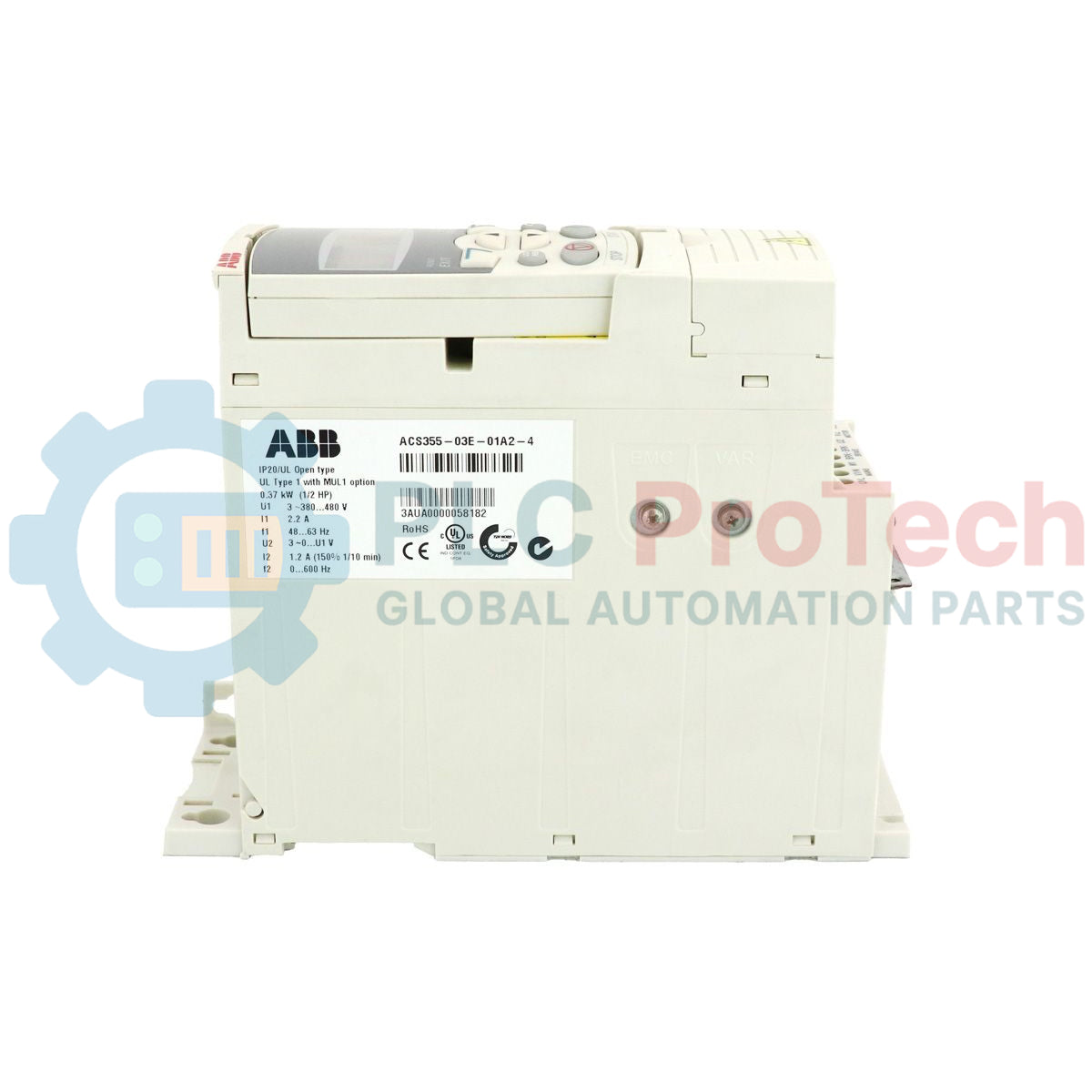
| Model / Article Number |
ACS355-03E-01A2-4 |
| Product Series |
ACS355 Machinery Drive |
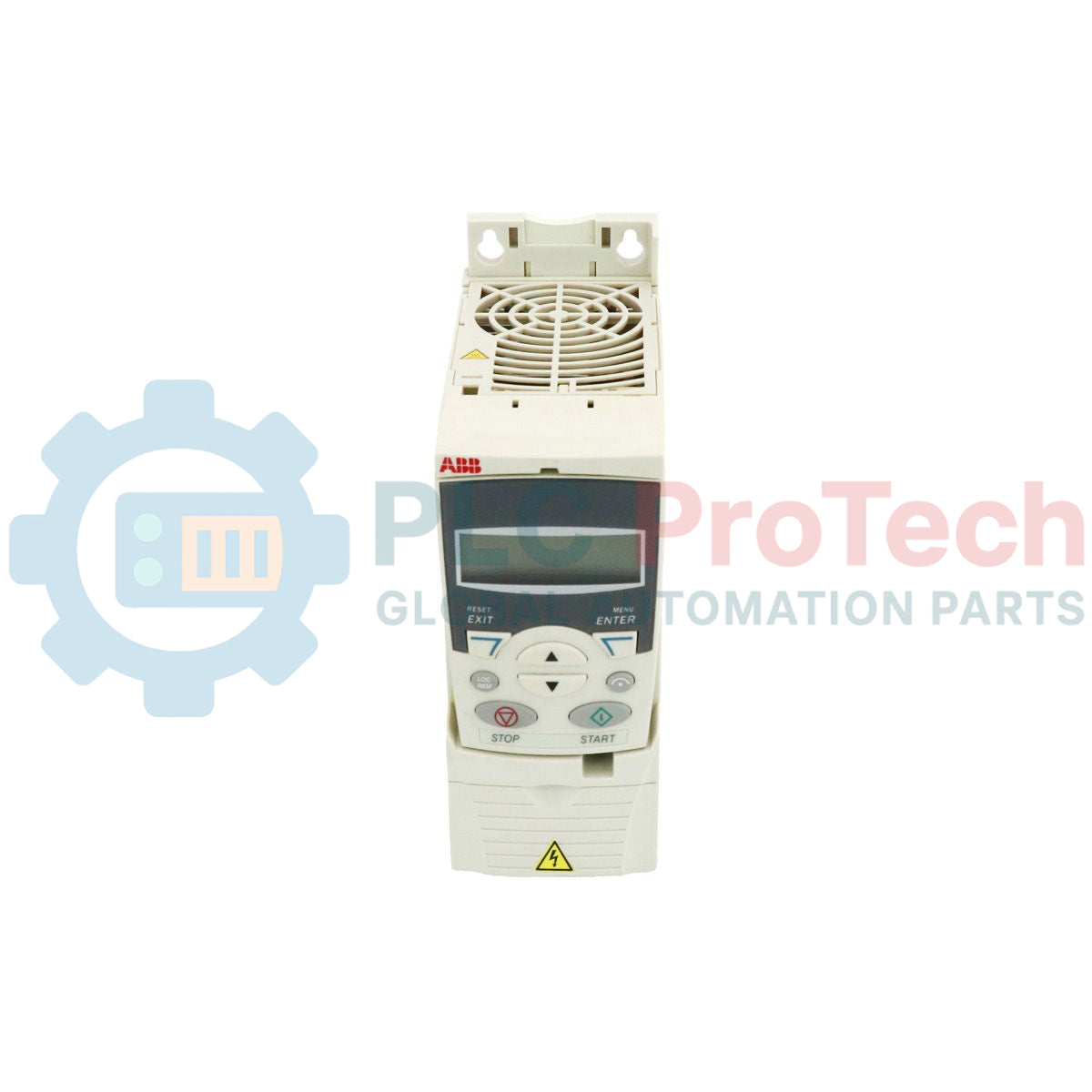
| Frame Size |
R0 |
| Enclosure Rating |
IP20 / UL Open Type |
| Input Voltage |
3-phase 380 to 480 VAC (+10% / -15%) |
| Input Frequency |
48 to 63 Hz |
| Nominal Output Power |
0.37 kW (0.5 HP) |
| Nominal Output Current |
1.2 A |
| Overload Capacity |
1.5 x nominal current (1.8 A) for 1 minute every 10 minutes |
| EMC Protection |
Integrated C3 Filter (for European and industrial grids) |
| Control Interfaces |
5 Digital Inputs, 2 Analog Inputs, 1 Analog Output, 1 Relay Output, 1 Transistor Output |
| Shipping Weight |
1.20 kg |
| Physical Dimensions |
169 mm (H) x 70 mm (W) x 161 mm (D) |
Connections and Interfaces
| Terminal Group |
Designation |
Functional Assignment |
| Power Terminals |
U1, V1, W1 |
3-phase mains supply input (380 to 480 VAC) |
| U2, V2, W2 |
Motor connection terminals |
| BRK+, BRK- |
External dynamic braking resistor terminals |
| Control & Safety I/O |
DI1 ... DI5 |
Configurable digital inputs (24 VDC PNP/NPN) |
| AI1, AI2 |
Analog reference inputs (0 to 10 V, 0 to 20 mA) |
| X1D (STO) |
Dual-channel Safe Torque Off connections (OUT1, OUT2, IN1, IN2) |
Empirical Engineering Insights
Alternative Models & Compatibility
The ACS355-03E-01A2-4 directly replaces legacy ACS350-03E-01A2-4 models. Footprints and wiring locations are fully identical. Note that parameter migration requires an ABB FlashDrop tool (MFDT-01) or a DriveWindow Light setup, as the internal parameter indexes differ slightly in the firmware between the ACS350 and ACS355 series.
Application Pitfalls & Engineering Notes
The R0 frame size depends entirely on internal convection fans and heat dissipation channels. When installing multiple drives side-by-side in a control panel, verify that the horizontal clearance is maintained at 0 mm only if the surrounding air temperature stays below 40 degC. If ambient temperatures inside the cabinet reach 40 to 50 degC, output current must be derated by 1% for every 1 degC exceeding the nominal limit.
Commissioning & Wiring Tips
For optimal safety performance, do not bypass the Safe Torque Off (STO) terminals. If STO is not connected to a dual-channel safety relay, the pre-installed factory jumpers must remain firmly placed across the X1D terminal block, otherwise, the drive will trigger fault code F0021 (STO active) and inhibit startup. Always run shielded motor cable and secure a 360-degree ground clamp at the drive's grounding plate to eliminate EMI feedback to weak analog loops.
Installation Guidelines
CRITICAL WARNING: Hazardous voltages remain present on the internal DC bus capacitors even after mains isolation. Disconnect input power and wait a minimum of 5 minutes for capacitive discharge before opening the front cover or initiating wiring adjustments.
1
Secure the drive to the DIN rail or backplate vertically. Ensure 75 mm of free space above and below the cooling vents.
2
Connect the protective earth (PE) terminals of both the input supply line and the motor frame to the drive's grounding points.
3
Wire the 3-phase incoming power lines to terminals U1, V1, and W1. Connect shielded motor power cables to terminals U2, V2, and W2.
4
Complete control terminal wiring (X1A / X1B) using twisted-shielded instrumentation cables for all analog speed references.