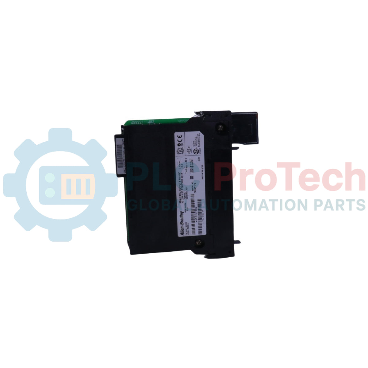
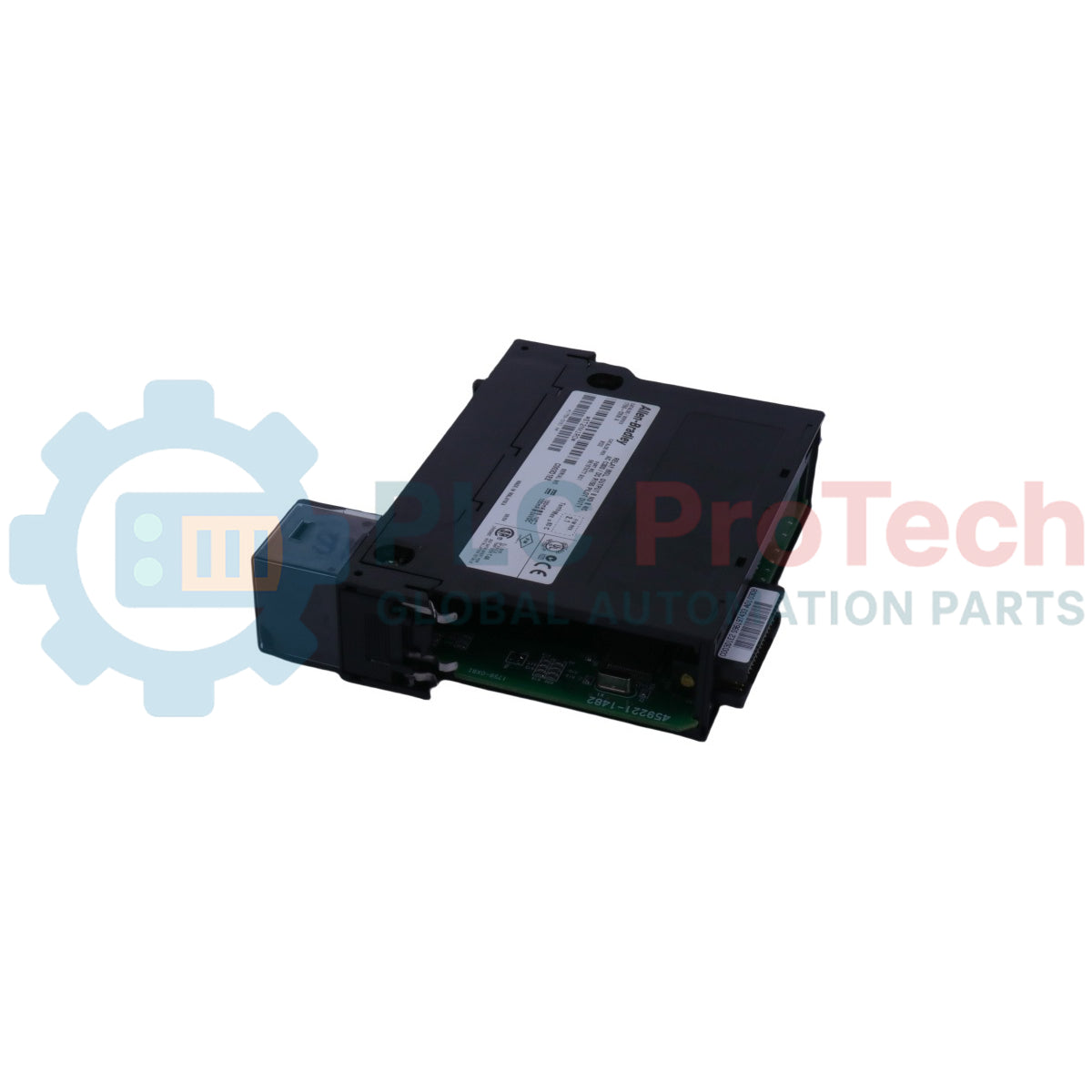
Das Allen-Bradley 1756-OX8I-Modul bietet acht isolierte digitale Ausgangskontakte, die für die Integration in ControlLogix-Systeme ausgelegt sind. Dieses Gerät unterstützt sowohl AC- als auch DC-Spannungsbereiche und ermöglicht die Steuerung in vielfältigen industriellen Anwendungen. Der 1756-OX8I verfügt über einzeln isolierte Ausgangsgruppen, die einen sicheren und zuverlässigen Betrieb in komplexen elektrischen Umgebungen gewährleisten. Entwickelt für nahtlose Kompatibilität mit ControlLogix-Backplanes, erleichtert das Modul die einfache Installation und Wartung in Automatisierungsarchitekturen. Dieses Modul ist ideal für Anwendungen, die robuste Kontakt-Ausgänge erfordern, wie relaisbasierte Betätigung, Statusanzeige und Kleinmotorsteuerung. Sein isoliertes Design minimiert Masseschleifen und erhöht die Störfestigkeit, was es für anspruchsvolle industrielle Umgebungen geeignet macht.
Einzeln isolierte Ausgangsgruppen (zwei Punkte pro Gruppe) zur Minimierung elektrischer Störungen.
Betrieb mit breitem Spannungsbereich: AC (10...240 V) oder DC (5...125 V).
Hohe Pilotlastbewertung (C300/R150) für zuverlässiges Schalten.
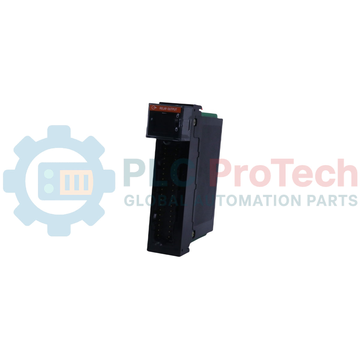
Enthält Statusanzeigen für Fehlerzustand und geplante Ausgänge.
Softwarekonfigurierbare elektronische Verriegelung zur Verhinderung falscher Modulinstallation.
Offenes Gehäusedesign für effiziente Wärmeabfuhr.
Anwendungen
Steuerung externer Relais, Magnetventile und Schütze.
Bereitstellung von Statusausgängen für Prozessinstrumentierung.
Ansteuerung von Kontrollleuchten oder akustischen Alarmen.
Schnittstelle zu nicht-PLC-gesteuerten Maschinen in Hybridsystemen.
Kleinmotor-Start/Stopp-Steuerung in isolierten Schaltkreisen.
Technische Daten
Attribut
Wert
Ausgänge
8 N.O. (normalerweise offen), einzeln isoliert (zwei Punkte pro Gruppe)
Pilotlast
C300/R150
Betriebsspannungsbereich
5...125 V DC10...240 V AC
Kontaktstrombewertung
1 A bei 5...30 V DC0,5 A bei 48 V DC0,22 A bei 125 V DC1,5 A bei 250 V AC 50/60 Hz0,75 A bei 480 V AC 50/60 Hz
Ausgangsverzögerungszeit
Aus zu Ein: max. 13 msEin zu Aus: max. 13 ms
Stromaufnahme
@ 5,1 V: 800 mA@ 24 V: 100 mA
Gesamtleistung Backplane
2,9 W
Maximale Leistungsaufnahme
3,1 W bei 60 °C (140 °F)
Wärmeabgabe
10,57 BTU/h
Leckstrom im Aus-Zustand
0 mA
Minimaler Laststrom
10 mA pro Punkt
Maximaler Anfangskontaktwiderstand
100 mOhm bei 6 V 1 A
Maximale Schaltfrequenz
1 Vorgang/3 s (0,3 Hz bei Nennlast)
Prellzeit, Mittelwert
1,2 ms
Erwartete Kontaktlebensdauer
300.000 Zyklen resistiv100.000 Zyklen induktiv
Geplante Ausgänge
Synchronisation innerhalb von 167,6 ms, bezogen auf die koordinierte Systemzeit
Zustände im Fehler-Modus pro Punkt
Letzten Zustand halten, Ein oder Aus (Aus ist Standard)
Zustände im Programmiermodus pro Punkt
Letzten Zustand halten, Ein oder Aus (Aus ist Standard)
Isolationsspannung
250 V (kontinuierlich), Basisisolierungstyp, Ausgänge zum Backplane und Ausgang zu Ausgang
Modul-Verriegelung
Elektronisch, softwarekonfigurierbar
Verschmelzen
Nicht geschützt. Eine abgesicherte IF6H wird empfohlen, um die Ausgänge zu schützen.
Abnehmbarer Anschlussblock
1756-TBCH1756-TBS6H
RTB-Schlüsselung
Benutzerdefinierte mechanische
Schlitzbreite
1
Leiterkategorie
p(1)
Gehäusetyp
Keine (offener Stil)
Nordamerikanischer Temperaturcode
T4A
(1) Verwenden Sie diese Leiterkategorie-Informationen zur Planung der Leiterführung wie im System-Installationshandbuch beschrieben. Siehe Industrial Automation Wiring and Grounding Guidelines, Publikation 1770-4.1.
10 V/m mit 1 kHz Sinuswelle 80% AM von 80...2000 MHz10 V/m mit 200 Hz 50% Puls 100% AM @ 800 MHz10 V/m mit 200 Hz 50% Puls 100% AM @ 880 MHz30 V/m mit 1 kHz Sinuswelle 80% AM von 2000...2700 MHzIEC 61000-4-3
EFT/Burst-Störfestigkeit
+-4 kV bei 5 kHz an SignaleingängenIEC 61000-4-4
Überspannungs-Störfestigkeit
+-1 kV Leitung-Leitung (DM) und +-2 kV Leitung-Erde (CM) an SignaleingängenIEC 61000-4-5
Geleitete HF-Störfestigkeit
10 V RMS mit 1 kHz Sinuswelle 80% AM von 150 kHz...80 MHzIEC 61000-4-6
Zertifizierungen
Zertifizierung(1)
Details
cULus
UL-gelistete Industrie-Steuergeräte, zertifiziert für USA und Kanada. Siehe UL-Datei E48599.UL-gelistet für Klasse I, Division 2 Gruppe A,B,C,D Gefahrenbereiche, zertifiziert für USA und Kanada. Siehe UL-Datei E49480.
CE
Europäische Union 2014/30/EU EMV-Richtlinie, konform mit:• EN 61326-1: Elektrische Geräte für Mess-, Steuer- und Laborzwecke. Industrielle Anforderungen• EN 61000-6-2: Industrielle Störfestigkeit• EN 61000-6-4: Industrielle Emissionen• EN 61508-2: Programmierbare Steuerungen (Abschnitt 8.2 Zone A & B)• EN 61508-2: Programmierbare Steuerungen (Abschnitt II)
RCM
Europäische Richtlinie 2014/35/EU Niederspannungsrichtlinie, konform mit EN 61010-2: Programmierbare SteuerungenAustralisches Funkkommunikationsgesetz, konform mit EN 61000-6-4: Industrielle Emissionen
FM
FM-zugelassene Ausrüstung für den Einsatz in Gefahrenbereichen der Klasse I Division 2 Gruppe A,B,C,D
KC
Koreanische Registrierung von Rundfunk- und Kommunikationstechnik, konform mit Artikel 58-2 des Funkwellen-Gesetzes, Absatz 3
UKCA
In Übereinstimmung mit den folgenden britischen Rechtsverordnungen und deren Änderungen:• 2016 Nr. 1091: Verordnung zur elektromagnetischen Verträglichkeit• 2016 Nr. 1101: Verordnung über elektrische Geräte (Sicherheit)• 2016 Nr. 107: Verordnung über Geräte und Schutzsysteme zur Verwendung in explosionsgefährdeten Bereichen• 2012 Nr. 3032: Beschränkung der Verwendung bestimmter gefährlicher Stoffe in elektrischen und elektronischen Geräten
Marokko
Ministerielle Verordnung Nr. 04-15 vom 1. Muharram 1437 (15. Oktober 2015)Anwendungsbestimmungen zum Schutz von Geräten vor SpannungseinflüssenMinisterielle Verordnung Nr. 04-15 vom 29. Ramadan 1436 (16. Juli 2015)Elektromagnetische Verträglichkeit von Geräten
(1) Wenn das Produkt vermarktet wird. Siehe den Link zur Produktzertifizierung unter <a href="#">ra.rockwellautomation.com</a> für Konformitätserklärungen, Zertifikate und weitere Zertifizierungsdetails.
Anschlüsse und Schnittstellen
Stecker / Klemme
Funktion / Schaltungszuordnung
Versorgungsanschlüsse
• L1-0 bis L1-7: Isolierte AC/DC-Versorgungs-Massen (auf Länge zuschneidbar)• DC-2 (H): Isolierte DC-Versorgungs-Masse (auf Länge zuschneidbar)
• Brückenleiste: Zum Durchschleifen der L1-Versorgung zu benachbarten RTBs
Hinweis: Die Verbindungen erfolgen über den abnehmbaren 36-poligen Klemmenblock (1756-TBCH oder 1756-TBS6H).
Richtlinien für die Feldinstallation
KRITISCHE RISIKOBEWERTUNG: ARC FLASH-GEFAHR UND EXPLOSIONSRISIKO. Trennen Sie keine mechanischen Verdrahtungsverbindungen und schieben Sie den abnehmbaren Klemmenblock (RTB) nicht von den Verriegelungssteckern ab, solange aktive Netzspannungen die Kontaktanschlussblöcke versorgen. Hochpotentielle Energiefelder an Relais-Ausgangsstiften können Lichtbögen erzeugen, die das Modul zerstören oder lokale Stromunterbrechungen auslösen.
1
Chassis-Ausrichtung: Richten Sie die Kunststoff-Kartenführungen des Moduls an den oberen und unteren Kanälen des Zielslots im 1756 ControlLogix-Chassis aus.
2
Einrichte-Mechanismus: Schieben Sie die Baugruppe fest nach innen, bis die strukturellen Verriegelungslaschen sicher einrasten und den Doppelstecker-Kern mit der aktiven Backplane-Schnittstelle verbinden.
3
Feldkabelanschluss: Entfernen Sie die Isolierung Ihrer Feldkabel auf die passende Länge, führen Sie die isolierten AC/DC-Stromleitungen auf die spezifischen 36-poligen RTB-Klemmenblöcke auf und ziehen Sie die Klemmenschrauben mit dem vorgeschriebenen Drehmoment fest.
4
Überspannungsschutz: Installieren Sie externe Überspannungsschutzgeräte (wie Varistoren oder Snubber) direkt über induktiven Feldlasten, um die internen mechanischen Relaiskontakte vor Hochspannungs-Induktionsrückschlägen zu schützen.
5
RTB-Anschluss: Schieben Sie den vormontierten 1756-TBCH- oder 1756-TBSH-Block direkt über die Schnittstellenstifte, klappen Sie die Verriegelungslasche ein und ziehen Sie die zentralen Befestigungsschrauben fest, um die Feldschnittstelle zu sichern.
Technical Datasheet (PDF)Complete specifications and technical drawings.
Was ist der Hauptvorteil der individuellen Kanal-zu-Kanal-Isolierung bei dieser Relaisbaugruppe?
Sie bietet eine vollständige elektrische Trennung zwischen den Punkten. Dadurch können Sie verschiedene AC-Leitungsphasen, Spannungsquellen oder unabhängige DC-Massennetze sicher innerhalb eines einzigen physischen Moduls mischen, ohne Übersprechen oder Kurzschlüsse.
Unterstützt dieses Kontaktmodul einen sofortigen Austausch im Feld bei eingeschalteter Chassis-Stromversorgung?
Ja. Das Modul ist vollständig darauf ausgelegt, den Austausch unter Spannung (Removal and Insertion Under Power, RIUP) zu unterstützen. Sie können die Hardware austauschen, ohne den Betrieb der restlichen Verarbeitungsracks zu unterbrechen.
Warum wird eine externe Überspannungsunterdrückung für die Kontaktpunkte empfohlen?
Relaiskontakte sind anfällig für Verschleiß durch elektrische Lichtbögen beim Schalten induktiver Lasten wie Magnetventile oder Spulen. Das Hinzufügen einer externen Unterdrückung verlängert die Lebensdauer der Kontakte und hält hochfrequente Schaltgeräusche von der lokalen Elektronik fern.
Globaler Expressversand
Standardlieferung: 4-6 Werktage per DHL, FedEx und UPS.
Expressversand: Versand am selben Tag für vorrätige Bestellungen, die vor 14:00 Uhr (GMT+8) aufgegeben werden.
Weltweite Abdeckung: Wir beliefern über 150 Länder, einschließlich schneller Lieferung nach Saudi-Arabien und in die VAE.
Rückgaben & Garantie
30-Tage-Garantie: Rückgaben werden für vorrätige Produkte in originaler, werkversiegelter Verpackung akzeptiert.
12-Monats-Garantie: Jede Industriekomponente ist durch unsere professionelle technische Garantie abgesichert.
Bestellungen werden von Montag bis Freitag bearbeitet und geliefert (außer an Feiertagen).
Für vollständige Anspruchsvoraussetzungen, Wiedereinlagerungsgebühren und internationale Rückgabedetails sehen Sie bitte unsere offiziellen
Rückerstattungs- & Rückgabebedingungen
.
Ein praktischer Leitfaden zum Austausch alter Bailey Symphony-Bedienstationen, die auf OpenVMS Alpha laufen. Er vergleicht Alpha-Emulation, OpenVMS x86-Migration, OPC-Neuplattformierung und...
Wartungsdaten verbinden Arbeitsaufträge, Sensorsignale, Anlagenhistorie, Kosten und das Wissen der Techniker. Richtig genutzt verbessern sie die Planung, Zuverlässigkeit, vorausschauende Wartung,...
Dieser Artikel erklärt, wie integrierte elektrische Aktuatoren, wie die e-Actuator-Serie von SMC, die industrielle Bewegungssteuerung revolutionieren, indem sie herkömmliche pneumatische und...
Dieser Artikel erklärt, wie SPS-Systeme grundlegende mathematische Operationen wie Addition, Subtraktion, Multiplikation, Division, Modulo und Potenzierung in der industriellen Automatisierung...
Der Artikel erklärt mehrere erweiterte Boolesche Logikfunktionen, die in der SPS-Programmierung über die grundlegenden AND-, OR- und NOT-Operationen hinaus verwendet werden. Er behandelt, wie...
Boolesche Logik ist die Grundlage jedes SPS-Programms. Von einfachen Maschinensteuerungen bis hin zu komplexen industriellen Automatisierungssystemen bestimmen Logikgatter, wie Steuerungen auf sich...
Die Auswahl einer Option führt zu einer vollständigen Seitenaktualisierung.