Description
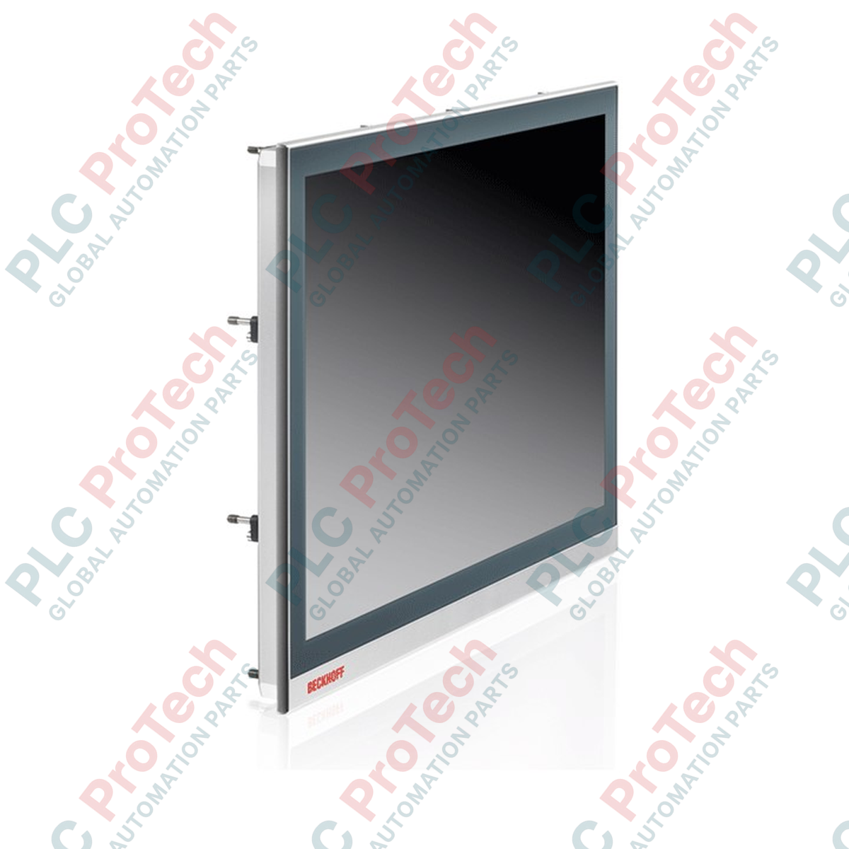
Integrating seamless operator interfaces with long-distance signal transmission, the Beckhoff C9900-F948 acts as a high-performance connectivity option for industrial multi-touch Control Panels. This interface module utilizes DVI/USB Extended (DVI-E/USB-E 2.0) physical layer conversion to extend digital video and peripheral signals up to 50 meters from the industrial PC without signal degradation. By leveraging high-quality copper cabling infrastructures, it allows remote mounting of high-resolution displays directly at the machine face while housing the PC safely in a centralized control cabinet, ensuring robust industrial operation in electromagnetically noisy environments.
Key Features
-
Extended Signal Range: Supports distance connections up to 50 meters between the Control Panel and the Industrial PC.
-
Standard Video Compatibility: Integrated DVI-E input compatible with standard PC DVI output interfaces.
-
High-Speed USB Transmission: USB-E 2.0 protocol layer transmits data at up to 480 Mbit/s.
-
Comprehensive Local I/O: Interfaces directly with multi-finger touch screens and integrated local USB ports.
-
Industrial Protection: Front-side IP65 and rear-side IP20 ingress protection ratings when properly panel-mounted.
Industrial Applications
- Automotive assembly lines and robotic work cells requiring remote HMIs.
- Food, beverage, and packaging machinery needing washdown-compatible front-panel mounting.
- Centralized plant floor control rooms with isolated processing units.
- Oil, gas, and chemical processing facilities utilizing physical environmental separation.
Technical Specifications
| Parameter |
Value |
| Manufacturer |
Beckhoff Automation |
| Model Number |
C9900-F948 |
| Device Type |
Multi-touch built-in Control Panel with DVI/USB Extended interface |
| Maximum Cable Distance |
50 meters (DVI-E and USB-E 2.0) |
| Input Interfaces |
1 x DVI-E, 1 x RJ45 (USB-E 2.0), 1 x USB 3.0 (up to 5m PC connection) |
| Local Output Interfaces |
2 x USB 3.0 (limited to USB 2.0 speeds at distances exceeding 3m) |
| Operating Supply Voltage |
24 V DC |
| Operating Temperature |
0 to 55 degC |
| Protection Rating |
IP65 Front, IP20 Rear |
| Shipping Weight (Calculated) |
3.0 kg |
| Package Dimensions (Calculated) |
280 x 210 x 95 mm |
Connections and Interfaces
| Connector / Port |
Functional Assignment |
| DVI Input Port |
Digital video input connection from Industrial PC transmitter module |
| RJ45 (USB-E 2.0) Port |
Receives high-speed USB extension signaling from IPC over Cat.6A/Cat.7 cable |
| Local USB 3.0 Type-A |
Direct local connection to peripherals (e.g., keyboard, flash drives, mouse) |
| Power Input Terminal |
Removable 24 V DC terminal block for system logic supply |
Empirical Engineering Insights
Alternative Models & Compatibility
The C9900-F948 DVI-E/USB-E interface represents an analog-over-copper physical layer extension. Ensure that the host Industrial PC is equipped with a compatible transmitter card, such as the CU8801 or C9900-U209, to correctly drive the signals. Note that this architecture is physical-signal-based and is not compatible with modern CP-Link 4 single-cable interfaces, which digitize and multiplex signals through PCIe protocol layers.
Application Pitfalls & Engineering Notes
When deploying the C9900-F948 at or near its maximum distance limit of 50 meters, standard patch cords should be avoided. Users must install high-quality double-shielded STP (Shielded Twisted Pair) Cat.6A or Cat.7 cables. High electromotive forces generated by adjacent variable frequency drives (VFDs) can disrupt USB handshake timing, resulting in touch interface dropouts or temporary display synchronization loss.
Commissioning & Wiring Tips
To ensure stable operation, the functional earth grounding stud of the display panel housing must be bonded back to the main control panel ground plate using a low-impedance copper strap. Ensure that the RJ45 metal shield is crimped properly to the ground casing on both ends of the Cat.6A/Cat.7 run to establish continuous path screening against high-frequency electrical noise.
Installation Guidelines
CRITICAL WARNING: Ensure all 24 V DC power supplies feeding the Control Panel and the host Industrial PC are fully de-energized before connecting or disconnecting any high-frequency data cables. Hot-plugging the DVI-E or RJ45 lines under load can induce electrostatic discharges, damaging the transceiver chipsets.
1
Mount the Control Panel into the designated cabinet cutout, securing the housing with the integrated pull-out clamping levers to achieve front-side IP65 seal pressure.
2
Securely connect the functional earthing wire to the rear housing ground stud.
3
Route the STP RJ45 cable and the DVI-E video cable through dedicated, noise-shielded cable trays, keeping them isolated from power conductors.
4
Plug in the power terminal block, verify the 24 V DC potential and polarity, and power up the host PC followed by the display console.