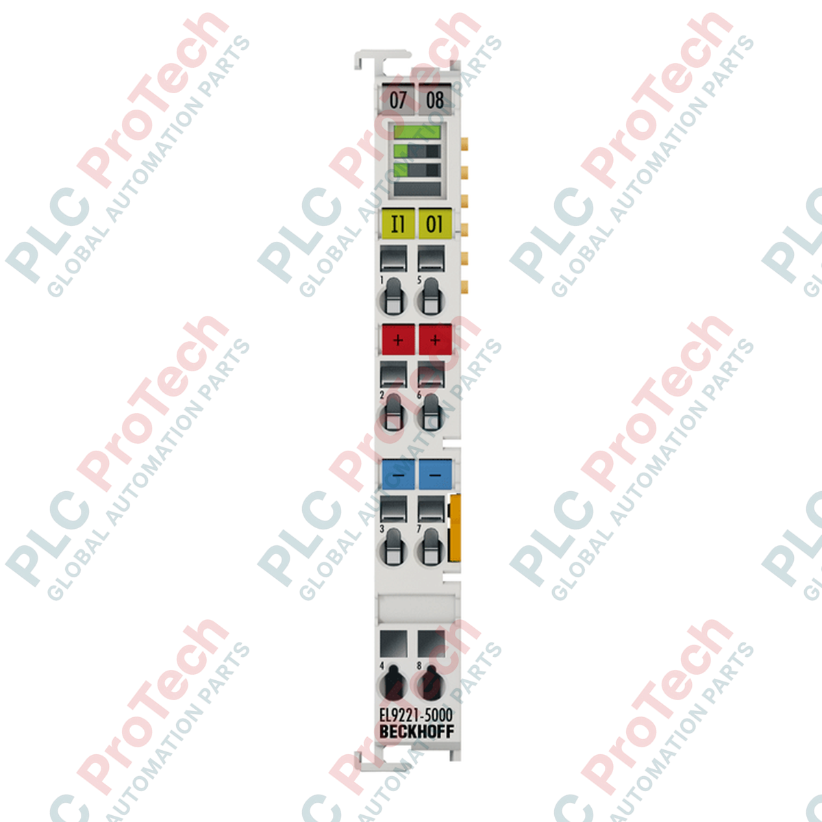
Entwickelt für selektiven Überstromschutz in 24 V DC-Steuerkreisen bietet das Beckhoff EL9221-5000 EtherCAT-Terminal eine aktive elektronische Überwachung und Abschaltfunktion für einen einzelnen elektrischen Kanal. Dieses kompakte 12-mm-Modul fügt sich nahtlos in das Standard-EtherCAT-Terminalsegment ein und bietet einstellbare Stromstärken von 1 bis 10 A, um empfindliche Feldgeräte vor Kurzschlüssen und Überlastungen zu schützen.
Hauptmerkmale
-
Einstellbarer Nennstrom: Konfigurierbar von 1 A bis 10 A in präzisen 1-A-Schritten über die integrierte LED-Tasten-Schnittstelle.
-
Aktive Strombegrenzung: Verhindert systemweite Spannungseinbrüche durch schnelle Isolierung von Fehlern am betroffenen Kanal.
-
E-Bus-Integration: Zieht typischerweise 80 mA vom E-Bus und ermöglicht vollständige Diagnose- und Statusmeldungen über TwinCAT.
-
Frühwarnsystem: Löst ein Warnsignal aus, wenn die Ausgangslast 90 % des eingestellten Schwellenwerts erreicht.
-
Integrierte Fehlersicherheit: Verfügt über eine eingebaute 15 A (F) Hardware-Sicherung als Sekundärschutz.
Industrielle Anwendungen
-
24 V DC Stromverteilung: Selektiver Schutz von Sensoren, Aktoren und Industrie-PC-Steuerungen.
-
Automobilmontagelinien: Segmentierter Schutz, um lokale Verdrahtungsfehler zu verhindern, die ganze Produktionslinien stoppen könnten.
-
Maschinenbau: Sichere Stromführung zu Hilfssteuerkreisen und Feldbusknoten.
Technische Spezifikationen
| Parameter |
Spezifikationswert |
| Hersteller |
Beckhoff Automation |
| Modellnummer |
EL9221-5000 |
| Nennspannung |
24 V DC |
| Anzahl der Kanäle |
1 Eingang, 1 Ausgang |
| Nennstrombereich |
Einstellbar von 1 bis 10 A (in 1-A-Schritten) |
| E-Bus-Stromaufnahme |
Typisch 80 mA |
| Elektrische Isolation |
500 V (E-Bus/Signalspannung) |
| Überspannungsabschaltung |
Größer oder gleich 32 V DC |
| Integrierte Sicherung als Rückfallebene |
15 A (schnell) |
| Betriebstemperatur |
0 bis 55 Grad Celsius |
| Lagertemperatur |
-25 bis 85 Grad Celsius |
| Schutzart |
IP20 |
| Abmessungen (B x H x T) |
12 mm x 100 mm x 68 mm |
| Gehäusematerial |
Polycarbonat |
| Zulassungen |
CE, cULus, cURus |
| Nettogewicht |
55 g |
| Versandgewicht (berechnet) |
0,15 kg |
Verdrahtungs- und Anschluss-Spezifikationen
| Anschlusstyp |
Leiterquerschnitt |
AWG-Bereich |
| Massivdraht (e) |
0,08 bis 2,5 mm² |
AWG 28 bis 14 |
| Feindrähtig (st) |
0,08 bis 2,5 mm² |
AWG 28 bis 14 |
| Flexible Leitung mit Aderendhülse (f) |
0,14 bis 1,5 mm² |
AWG 26 bis 16 |
| Abisolierlänge |
8 bis 9 mm |
Empirische Ingenieurhinweise
Alternative Modelle & Kompatibilität
Der EL9221-5000 verfügt über eine integrierte LED-Tasten-Schnittstelle zur lokalen manuellen Konfiguration und Statusanzeige, die ihn von Standard-Überstromanschlüssen mit festem Wert unterscheidet. Beim Einbinden dieses Moduls in bestehende TwinCAT-Systemmanager-Konfigurationen stellen Sie sicher, dass die korrekte XML-Gerätebeschreibung (ESI) geladen ist, um vollen Zugriff auf die Diagnose-Register und Strombegrenzungsparameter zu erhalten.
Anwendungsfallen & technische Hinweise
Beim nebeneinander montierten Betrieb mehrerer EL9221-5000 unter hohen Dauerstrombelastungen (bis zu 10 A pro Modul) muss die thermische Anhäufung im Gehäuse überwacht werden. Sorgen Sie für eine ausreichende Belüftung des Schaltschrankes. Beachten Sie, dass die 90%-Last-Vorwarnschwelle sehr empfindlich ist; transiente Anlaufströme induktiver Lasten sollten abgebildet werden, um Fehlwarnungen im SPS-Regelkreis zu vermeiden.
Inbetriebnahme- & Verdrahtungstipps
Verwenden Sie beim Verdrahten stets einen Standard-Schlitzschraubendreher, um den Spannklemmenmechanismus zu betätigen. Achten Sie darauf, dass das E-Bus-Strombudget des vorgelagerten EtherCAT-Kopplers (z. B. EK1100) nicht überschritten wird, da der EL9221-5000 nominal 80 mA vom internen Kommunikationsbus zieht.
Installationsrichtlinien
KRITISCHE WARNUNG
Schalten Sie alle Stromquellen vor der Montage, Demontage oder Verkabelung des Moduls spannungsfrei. Das Nicht-Isolieren der 24 V DC-Systemversorgung und der E-Bus-Versorgung kann zu dauerhaften Schäden an den Anschlusskontakten, benachbarten Modulen oder der EtherCAT-Koppler-Schnittstelle führen.
1
Montieren Sie den Anschluss auf einer Standard-35-mm-DIN-Schiene gemäß EN 60715 und stellen Sie sicher, dass der Verriegelungsmechanismus sicher einrastet.
2
Schieben Sie den Anschluss entlang der Schiene, um ihn mit dem benachbarten EtherCAT-Anschluss zu verbinden, und stellen Sie sicher, dass der Doppelschlitz- und Schlüsselsitz vollständig eingerastet ist.
3
Abisolieren Sie die Anschlussdrähte auf die angegebene Länge von 8 bis 9 mm. Führen Sie den Leiter mit einem Schraubendreher zur Betätigung in den federbelasteten Anschluss ein.
4
Schließen Sie eine 24 V DC-Stromversorgung an und konfigurieren Sie die gewünschte Strombegrenzung (1 bis 10 A) über die lokale LED-Taste oder die TwinCAT-Softwareoberfläche.