Description
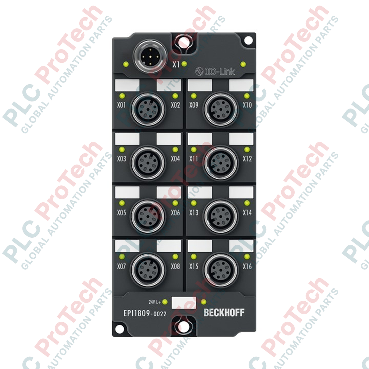
Facilitating decentralized field signal acquisition, the Beckhoff EPI1809-0022 interfaces sixteen 24 V DC digital inputs directly to an IO-Link master. This highly compact IO-Link box allows sensors to be connected directly in the field without requiring a protective electrical enclosure. The module operates as an IO-Link Class A device, exchanging process data and configuration parameters over a standardized point-to-point communication channel. The robust structural encapsulation ensures reliable functionality in harsh manufacturing zones where dust, moisture, and high mechanical vibration are prevalent.
Features
-
16 Digital Inputs: High-density distribution with Type 3 input characteristics according to EN 61131-2.
-
IO-Link V1.1 Compliance: Supports the Class A specification with high-speed COM3 communication rates.
-
Configurable Filters: Input filter times are adjustable from 0 to 20 ms to accommodate various sensor responses.
-
Integrated Sensor Protection: A collective 0.5 A sensor supply is fully protected against short-circuit events.
-
Heavy-Duty Seal: IP65, IP66, and IP67 protection ratings enable direct field mounting.
Applications
- Automotive assembly lines and conveyor networks.
- Decentralized input monitoring on large packaging machinery.
- Machine-mount sensor aggregation in washdown or wet processing areas.
- Robotic end-of-arm tooling requiring lightweight signal hubs.
Technical Specifications
| Parameter |
Specification Value |
| Manufacturer |
Beckhoff Automation GmbH & Co. KG |
| Model Number |
EPI1809-0022 |
| Communication Protocol |
IO-Link |
| IO-Link Specification Version |
V1.1, Class A |
| Data Transfer Rate |
230.4 kbaud (COM3) |
| Primary Interface |
1 x M12 plug, A-coded |
| Number of Inputs |
16 |
| Input Connections |
M12, screw type |
| Nominal Input Voltage |
24 V DC (-15% / +20%) |
| Input Filter Range |
3.0 ms (default), adjustable from 0 to 20 ms |
| "0" Signal Voltage |
-3 to +5 V (EN 61131-2, type 3) |
| "1" Signal Voltage |
11 to 30 V (EN 61131-2, type 3) |
| Input Current |
Typical 3 mA (EN 61131-2, type 3) |
| Sensor Supply |
Maximum 0.5 A from L+, short-circuit proof in total |
| Current Consumption |
Typical 100 mA from L+ |
| Operating Temperature |
-25 to +60 Celsius |
| Storage Temperature |
-40 to +85 Celsius |
| Protection Rating |
IP65 / IP66 / IP67 (conforms to EN 60529) |
| Vibration & Shock Standards |
Conforms to EN 60068-2-6 and EN 60068-2-27 |
| EMC Immunity & Emission |
Conforms to EN 61000-6-2 and EN 61000-6-4 |
| Approvals |
CE, UL |
| Module Weight |
250 g |
| Shipping Weight |
2.0 kg |
| Country of Origin |
Germany |
Empirical Engineering Insights
Alternative Models & Compatibility
The EPI1809-0022 uses Class A port assignment. Note that when replacing an older EP1809-0022 module, the control system must be adapted because the EP series operates natively on EtherCAT (requiring an EtherCAT master and XML descriptions), whereas the EPI series uses the IO-Link physical protocol layer under a master gateway. Verify that the master IO-Link port pinout matches the standard Class A configuration before commissioning.
Application Pitfalls & Engineering Notes
A common issue in field installations is overloading the sensor supply line. While individual input current is restricted to typical Type 3 parameters (3 mA), the aggregate sensor supply is capped at 0.5 A. If several high-current photo-electric proximity sensors or ultrasonic transducers are powered directly from this unit, the short-circuit protection mechanism will engage, shutting down auxiliary sensor power. Ensure a power budget calculation is done for all 16 connected devices.
Commissioning & Wiring Tips
When pairing the device with non-Beckhoff IO-Link masters, ensure that the correct manufacturer IODD configuration file is loaded into the engineering software (such as TwinCAT or TIA Portal) to correctly map the 16-channel process image. Tighten all unused M12 connections with protective caps to maintain the IP67 integrity; failure to seal unused ports can allow condensation to bridge contacts over time, causing intermittent "0" and "1" signal faults.
Installation Guidelines
CRITICAL WARNING: Prior to commencing any mechanical mounting or cable connection steps, completely de-energize the main 24 V DC system supply line to the IO-Link master unit. Do not plug or unplug M12 cables while under electrical load, as contact-arcing could damage sensitive semiconductor components in the internal transceiver circuit.
1
Mount the module directly to a flat, vibration-resistant surface using two M4 screws through the integrated chassis mounting holes. Ensure the installation position allows for adequate cable strain relief.
2
Securely plug the A-coded M12 IO-Link communication cable into the module's communication port and hand-tighten the coupling nut.
3
Connect the 16 digital input sensors to the appropriate M12 input channels. Utilize standard torque wrenches for M12 connectors to guarantee environmental sealing without over-tightening.
4
Power up the master system and configure the corresponding input filter settings and channel maps within your automation development workspace.