Description
Designed for space-constrained industrial environments directly on the machine frame, the Beckhoff EPP1008-0022 is an EtherCAT P-coded digital input module that eliminates the need for localized field enclosures. It acquires fast digital control signals from the physical layer and transmits them to the control architecture over a unified, high-speed connection. By integrating data and power supply (both Us and Up) into a single 4-wire, P-coded M8 cable, this module optimizes cabling complexity while maintaining deterministic communication. Encased in a rugged polyamide housing, the device offers excellent resistance to environmental stressors, vibration, and moisture ingress.
Key Features
-
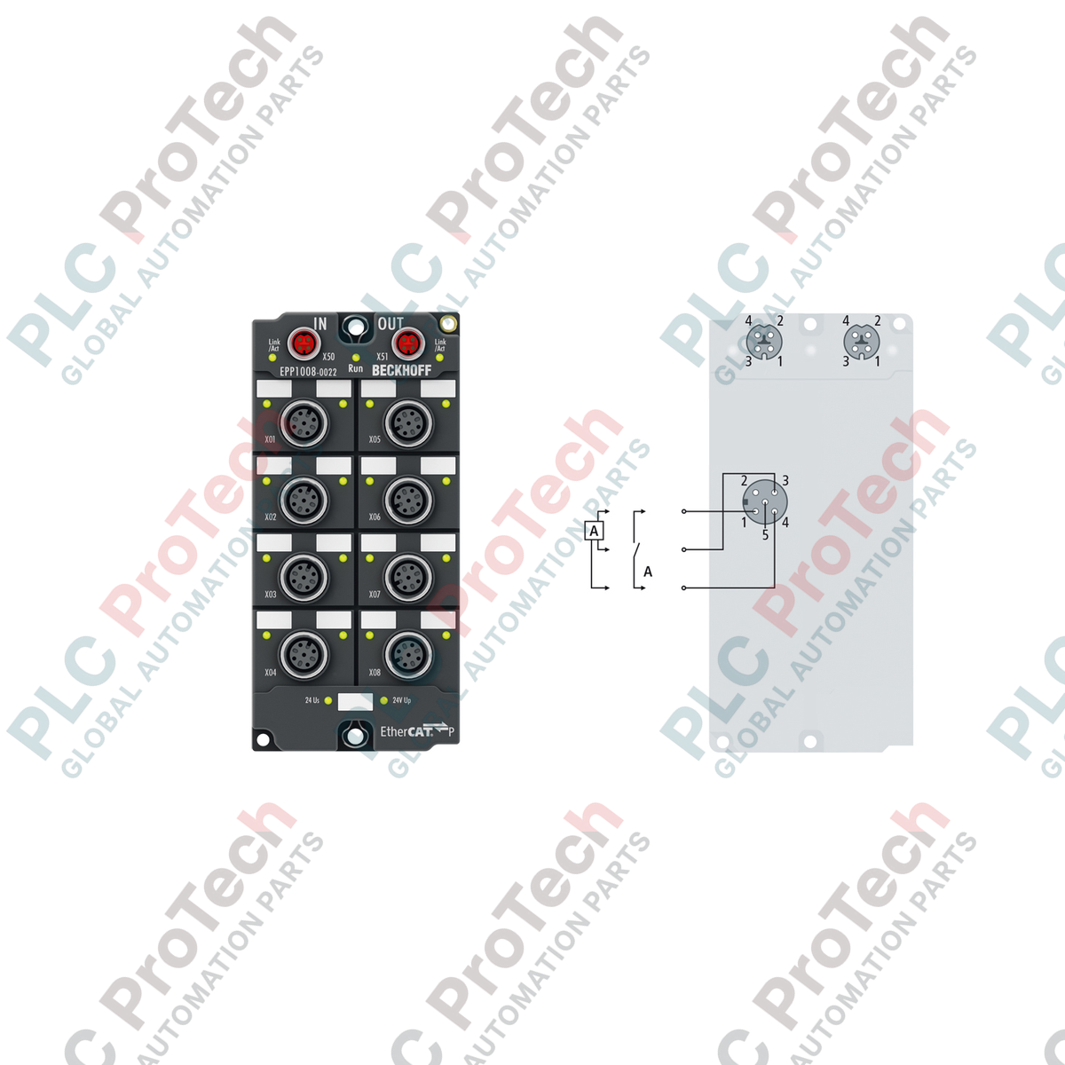
Unified EtherCAT P Interface: Combines EtherCAT Ethernet communication and power supply (24 V DC control Us and peripheral Up) on a single M8 socket.
-
Robust Signal Acquisition: 8 digital inputs conforming to EN 61131-2 Type 1/3 standards for highly reliable industrial signal logging.
-
Single-Input M12 Sockets: Direct 1-to-1 sensor mapping with 8 dedicated M12 A-coded 5-pin connectors, minimizing field wiring errors.
-
Short-Circuit Protection: Integrated 0.5 A sensor supply derived from the control voltage Us, fully protected against overcurrent and short-circuits.
-
Industrial-Grade Housing: IP65, IP66, and IP67-rated PA6 (polyamide) enclosure designed for direct mounting in harsh, washdown, or oily environments.
Applications
-
Decentralized Machine Tooling: Direct installation on CNC frames, stamping units, and robotic arms without protective enclosures.
-
Conveyor and Logistics Lines: Streamlined sensor collection along extended physical distances using single-cable daisy-chaining.
-
Automated Assembly Systems: Interfacing proximity switches, photoelectric barriers, and mechanical limit switches directly in the processing zone.
-
Wet and Washdown Areas: Food and beverage packaging lines requiring IP67 high-pressure cleaning resistance.
Technical Specifications
| Parameter |
Specification Value |
| Manufacturer |
Beckhoff Automation |
| Model Number |
EPP1008-0022 |
| Protocol |
EtherCAT P |
| Bus Interface |
2 x M8 socket, shielded, screw-type, P-coded |
| Number of Inputs |
8 digital inputs (1 input per physical M12 plug) |
| Input Specification |
EN 61131-2, Type 1/3 |
| Input Connections |
M12 x 1, 5-pin, A-coded |
| Nominal Input Voltage |
24 V DC (-15% / +20%) |
| Input Filter Time |
3.0 ms |
| "0" Signal Voltage Range |
-3 to +5 V DC |
| "1" Signal Voltage Range |
11 to 30 V DC |
| Typical Input Current |
3 mA (EN 61131-2, Type 3) |
| Sensor Power Supply |
Derived from control voltage Us, max. 0.5 A, short-circuit proof (total) |
| Current Consumption (from Us) |
Typically 100 mA |
| Electrical Isolation |
500 V RMS |
| Protection Class |
IP65 / IP66 / IP67 (conforms to EN 60529) |
| Housing Material |
PA6 (Polyamide) |
| Operating Temperature |
-25 to +60 degC |
| Storage Temperature |
-40 to +85 degC |
| Physical Dimensions |
60 mm x 126 mm x 26.5 mm (W x H x D) |
| Weight |
Approximately 250 g |
| Shipping Weight (Calculated) |
2.0 kg (with protective bulk export packaging) |
Connections and Interfaces
| Port Type |
Pin Number |
Functional Signal Designation |
| M8 (EtherCAT P) |
Pin 1 |
Transmission Data + (Tx+) / Control Voltage + (Us +24 V DC) |
| Pin 2 |
Receive Data + (Rx+) / Peripheral Voltage + (Up +24 V DC) |
| Pin 3 |
Receive Data - (Rx-) / Peripheral GND (GNDp) |
| Pin 4 |
Transmission Data - (Tx-) / Control GND (GNDs) |
| M12 (Digital Inputs) |
Pin 1 |
+24 V DC Sensor Supply Us |
| Pin 2 |
Not Connected (NC) |
| Pin 3 |
0 V GND Sensor Supply |
| Pin 4 |
Digital Input Signal (Channels 1 to 8) |
| Pin 5 |
Functional Earth (FE) / Shield |
Empirical Engineering Insights
Alternative Models & Compatibility
The EPP1008-0022 utilizes EtherCAT P, requiring P-coded M8 connections. It is not pin-compatible with standard EP1008-0002 modules, which use standard A-coded EtherCAT and external auxiliary power lines. If migrating from standard EtherCAT EP boxes to EPP boxes, verify that the master station integrates an EP9224 power feeder or EK1310 junction coupler to supply combined Us/Up power on the line.
Application Pitfalls & Engineering Notes
A common system-integration mistake involves exceeding the 3.0 A maximum current limit allowed for Us (Control Power) or Up (Peripheral Power) inside a daisy-chained EtherCAT P segment. When implementing long chains of EPP1008-0022 modules, use the TwinCAT System Manager software to calculate cumulative line-voltage drops. If the Us voltage drops below 20.4 V DC at the last node, intermittent field communication or sensor drops will occur.
Commissioning & Wiring Tips
Unlike some multi-input M12 blocks that share two signals per physical plug, the EPP1008-0022 contains strictly one input per M12 interface mapped exclusively to Pin 4. Standard, single-channel 3-wire sensors (PNP type) can be wired directly without customized Y-splitters. Ensure that all unused M12 and M8 ports are sealed with industrial screw caps to maintain the unit's IP67 environmental sealing integrity.
Installation Guidelines
CRITICAL WARNING: Prior to physically mounting or wiring the device, completely disconnect all power sources feeding the EtherCAT P line. Hot-plugging or hot-unplugging P-coded M8 modules under live load can cause electrical arcing, resulting in permanent damage to the internal EtherCAT P transceiver components and connected sensors.
1
Position the module on a flat, vibration-resistant machine frame. Secure using the top and bottom fixing holes. Utilize 2 x M3 bolts (for 3.5 mm holes) or 2 x M4 bolts (for 4.5 mm holes) torque-tightened to prevent mechanical loosening under high-frequency operation.
2
Connect the incoming EtherCAT P cable to the upper P-coded M8 socket, and run the outgoing daisy-chain segment from the lower M8 socket. Hand-tighten the M8 metal screw caps to ensure gas-tight connection and shield integrity.
3
Plug the digital M12 sensor cables into the appropriate 5-pin female ports. Tighten the knurled metal nuts to prevent moisture ingress. Seal any unused ports with protective plugs to preserve the IP67 specification.
4
Power on the EtherCAT P branch and check the LED status. Verify that the system "Us" and communication link indicators illuminate solid green, confirming established field communication and proper node supply.