Description
Designed for decentralised acquisition of binary signals in harsh physical environments, this industrial IO module interfaces directly with serial fieldbus systems. The Beckhoff IP1011-B730 distributes 8 digital inputs across a field-level footprint, transmitting state data over Modbus RTU/ASCII to standard industrial controllers. Operating at 24 V DC, it features short-circuit protected sensor power distribution and rapid 0.2 ms input filtering suitable for high-speed tracking.
Features
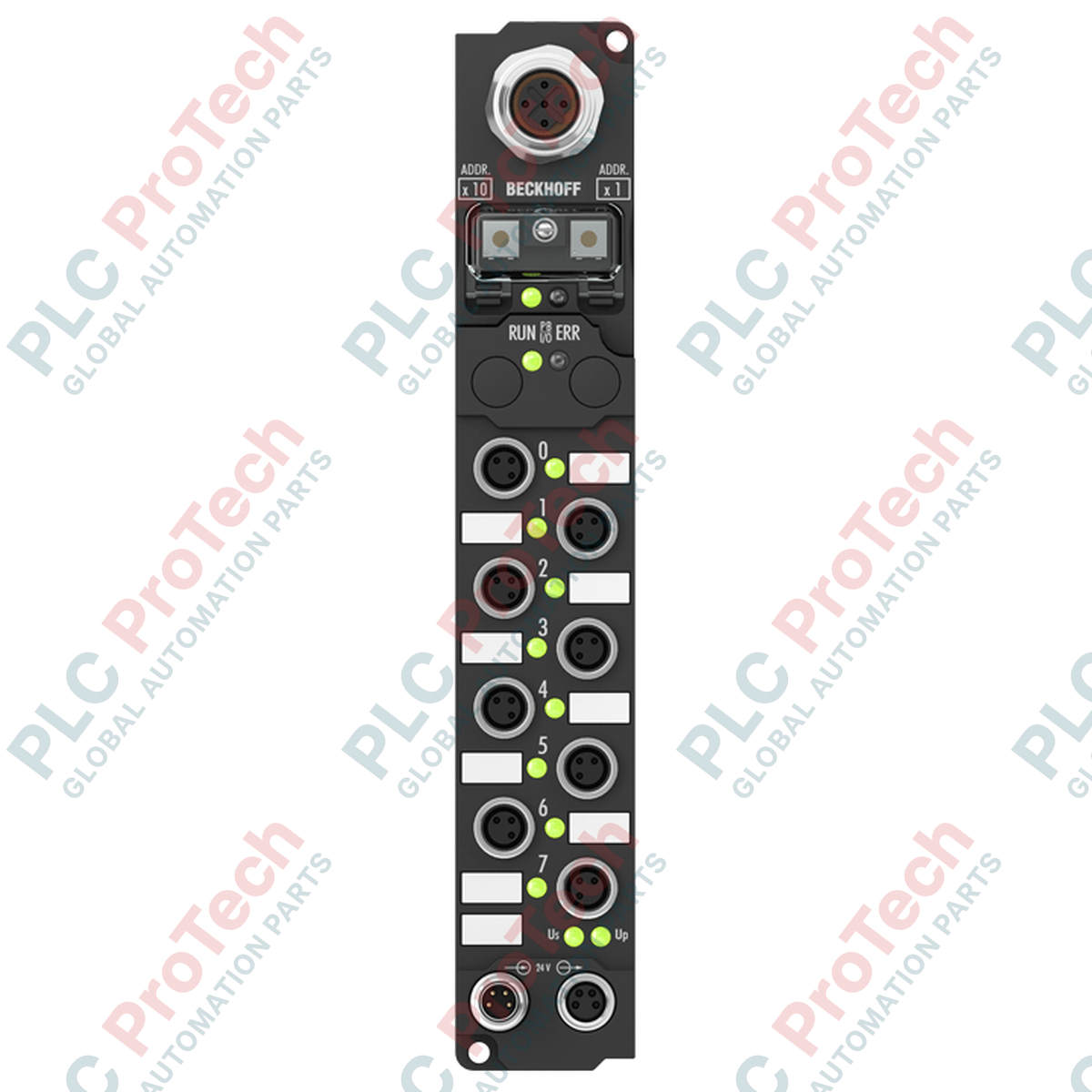
- 8 digital input channels with M8 screw-type connection interfaces
- Integrated Modbus fieldbus interface supporting RTU and ASCII protocols
- Wide-range input voltage compliance (-15% to +20%) conforming to EN 61131-2 Type 2
- Full IP65/66/67 environmental protection class for control cabinet-free installation
- Flexible address configuration via manual rotary switches or KS2000 software
Applications
- Field-level sensor aggregation in automotive manufacturing and assembly lines
- Distributed I/O processing in material handling conveyor networks
- Remote digital signal monitoring in municipal water and wastewater facilities
- On-machine wiring integration for packaging, sorting, and palletizing machinery
Technical Specifications
| Parameter |
Specification |
| Manufacturer |
Beckhoff |
| Part Number |
IP1011-B730 |
| Product Series |
Fieldbus Box |
| Number of Inputs |
8 |
| Connection Type |
M8 (Screw Type) |
| Input Filter |
0.2 ms |
| Nominal Voltage |
24 V DC (-15 % / +20 %) |
| "0" Signal Voltage |
-3 to +5 V (EN 61131-2, Type 2) |
| "1" Signal Voltage |
11 to 30 V (EN 61131-2, Type 2) |
| Input Current |
typ. 6 mA |
| Sensor Supply |
max. 0.5 A (short-circuit proof, total) |
| Protocol |
Modbus RTU / ASCII |
| Baud Rates |
150, 300, 600, 1200, 2400, 4800, 9600, 19200, 38400 baud |
| Bus Interface |
1 x M12 socket, 5-pin, B-coded |
| Box Supply Current |
45 mA + sensor current |
| Electrical Isolation |
Control voltage / fieldbus: Yes |
| Material |
PA6 (Polyamide) |
| Dimensions (W x H x D) |
30 mm x 175 mm x 26.5 mm |
| Operating Temperature |
0 to +55 degC |
| Storage Temperature |
-25 to +85 degC |
| Protection Class |
IP65/66/67 (conforms to EN 60529) |
| Weight |
approx. 210 g |
| Shipping Weight (Calculated) |
2.0 kg |
Connections and Interfaces
| Interface Connection |
Connector Type |
Function Assignment |
| Feed Power |
1 x M8 male socket, 4-pin |
Control voltage (24 V DC) supply input |
| Downstream Power |
1 x M8 female socket, 4-pin |
Control voltage loop-through to adjacent modules |
| Fieldbus Port |
1 x M12 socket, 5-pin, B-coded |
Modbus RTU/ASCII communication connection |
| Digital Inputs (0-7) |
8 x M8 screw-type sockets |
3-wire sensor connections (24V DC, GND, Signal) |
Alternative Models & Compatibility
The IP1011-B730 belongs to the Beckhoff Modbus Fieldbus Box family. It serves as a direct functional match for older IP1011 configurations using RS485 physical layer communication. While fully compatible with the standard TwinCAT software environments via Modbus master libraries, addressing must be configured manually via rotary switches or the KS2000 configuration cable interface when swapping units from different legacy systems.
Application Pitfalls & Engineering Notes
The total cumulative sensor supply current across all 8 M8 input connections must not exceed 0.5 A. Exceeding this combined rating trips the internal short-circuit protection, temporarily disabling power to all attached sensors. When deploying the unit in environments with significant electrical interference, ensure the RS485 shielding is properly grounded through the B-coded M12 connector casing to avoid message packet drops or CRC errors over Modbus.
Commissioning & Wiring Tips
Always configure the station address before mounting the module in inaccessible areas. The address switches are located beneath the clear protective cover on the face of the unit. Ensure the integrated elastomeric seal is properly seated in its groove when refastening the cover; failure to align this gasket compromises the IP67 moisture seal and may lead to fluid ingress and internal board corrosion.
Installation Guidelines
CRITICAL WARNING: De-energize all primary control and load power supplies before starting physical installation or wiring modifications. Failure to disconnect system power can cause terminal arcing, electrical shock, and damage to the internal bus transceiver circuitry.
1
Position the module onto a flat mounting surface and secure using two M3 screws through the 3.5 mm diameter fixing holes. Do not exceed 0.5 Nm of torque.
2
Remove the protective address cover, configure the network address via the rotary switches, and carefully re-secure the cover ensuring seal alignment.
3
Connect the B-coded M12 Modbus cable and secure the coupling ring to maintain the environmental IP rating.
4
Connect the 4-pin M8 power feed cable. If looping power to an adjacent module, connect the M8 downstream cable.
5
Plug in the M8 digital input sensor lines. Ensure unused ports are sealed with protective caps to maintain environmental integrity.