Description
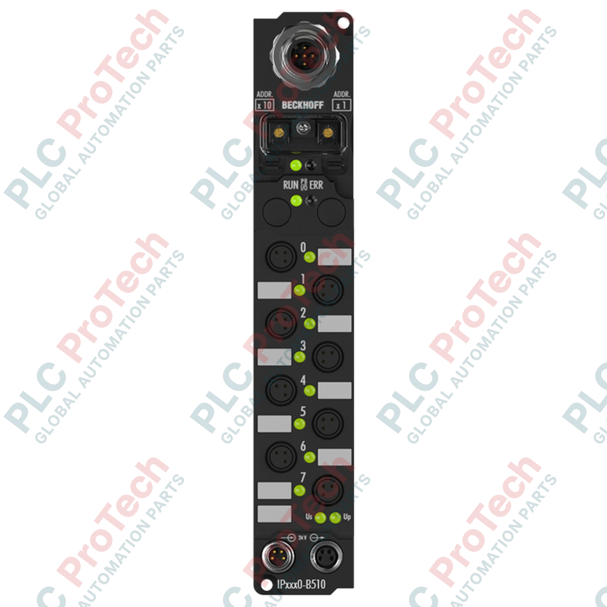
To facilitate distributed decentralized I/O acquisition in harsh industrial environments, the Beckhoff IP2300-B510 integrates discrete inputs and outputs directly at the machine level via a high-performance CANopen fieldbus interface. This compact Fieldbus Box module features 4 digital inputs with a 3 ms input filter alongside 4 digital outputs rated for 0.5 A, housing them within an IP67-rated enclosure designed to bypass the need for protective control cabinets. Connection is established using space-saving M8 connector sockets, minimizing cabling overhead and reducing transmission latency in decentralized automation topologies.
Features
- Direct integration into CANopen industrial networks via standard D-sub or M12 connection interfaces.
- Robust IP67 housing design, rendering the unit fully resistant to dust, moisture, and high-pressure washdown environments.
- Four integrated 24 V DC digital inputs featuring an integrated 3 ms hardware input filter to suppress signal contact bounce.
- Four short-circuit proof 24 V DC digital outputs capable of delivering up to 0.5 A continuous current per channel.
- Diagnostic LEDs mapping network activity, device operational status, and localized channel diagnostics.
- Simple rotary address switches for rapid node address configuration during commissioning.
Applications
- Automotive assembly lines and robotic tool-end I/O processing.
- Conveyor networks and packaging machinery requiring decentralized, machine-mount sensor consolidation.
- Material handling plants utilizing distributed CANopen topologies.
- Machine tool control lines subject to high coolant, oil, or particulate exposure.
Technical Specifications
| Specification Parameter |
Technical Value |
| Manufacturer |
Beckhoff |
| Model Identifier |
IP2300-B510 |
| Fieldbus System |
CANopen |
| Digital Inputs |
4 channels (24 V DC) |
| Input Filter Time |
3.0 ms |
| Digital Outputs |
4 channels (24 V DC, short-circuit proof) |
| Max. Output Current |
0.5 A per channel (total current limits apply) |
| I/O Connection Type |
M8 (diameter 8 mm circular connectors) |
| Operating Voltage |
24 V DC (control and load voltage feeds) |
| Ingress Protection Rating |
IP67 (when all slots are mated or capped) |
| Operating Temperature Range |
0 to 55 degC |
| Storage Temperature Range |
-25 to 85 degC |
| Shipping Weight (Calculated) |
2.0 kg |
| Package Dimensions (Calculated) |
220 mm x 110 mm x 60 mm |
Connections and Interfaces
| M8 Connector Pin |
Input Port Assignment |
Output Port Assignment |
| Pin 1 |
+24 V DC Sensor Supply |
Not Connected |
| Pin 2 |
Not Connected |
Auxiliary Ground Reference |
| Pin 3 |
GND Sensor Supply |
GND Load Supply |
| Pin 4 |
Digital Input Signal (DI1 to DI4) |
Digital Output Signal (DO1 to DO4) |
Empirical Engineering Insights
Alternative Models & Compatibility
The IP2300-B510 utilizes standard CANopen communication profiles. While mechanically identical to the IP2300-B310 (PROFIBUS DP) and IP2300-B900 (Ethernet), it requires a dedicated CANopen master or coupler to map PDOs/SDOs. If migrating from older legacy Beckhoff Fieldbus Box units, verify your network master's ESD (electronic data sheet) configuration files to ensure parameter mappings match the device profile.
Application Pitfalls & Engineering Notes
When deploying in wet or high-humidity environments, any unused M8 ports must be covered using IP67-rated protective caps. Leaving even a single port exposed compromises the environmental seal of the entire assembly, leading to moisture ingress and localized internal short circuits between the 24 V DC sensor supply line and ground.
Commissioning & Wiring Tips
Ensure that the CANopen network is terminated with a 120-Ohm resistor at both ends of the physical bus. If the IP2300-B510 is configured as the physical end-of-line node, a dedicated terminating M12 plug must be inserted. Always set the node ID via the address dial switches under the protective screw cap prior to powering on the control logic feed.
Installation Guidelines
CRITICAL WARNING
Isolate all electrical power sources (logic and field power loops) before mounting, cabling, or adjusting the address switches. Ground loops can induce network dropouts and permanently degrade the integrated output transistors.
1
Mount the IP2300-B510 module directly onto a flat, vibration-resistant machine frame using M4 mounting screws. Connect the chassis ground contact to the machine frame.
2
Set the designated CANopen node address and communication baud rate using the rotary switches under the front protective cover. Reseal the cover tightly.
3
Attach the M8 sensor and actuator cables, ensuring a secure thread lock is achieved on each connector to protect against moisture intrusion.
4
Connect the incoming CANopen network cable and power lines. Turn on the 24 V DC system logic and perform testing sequences via your PLC's network master.