Description
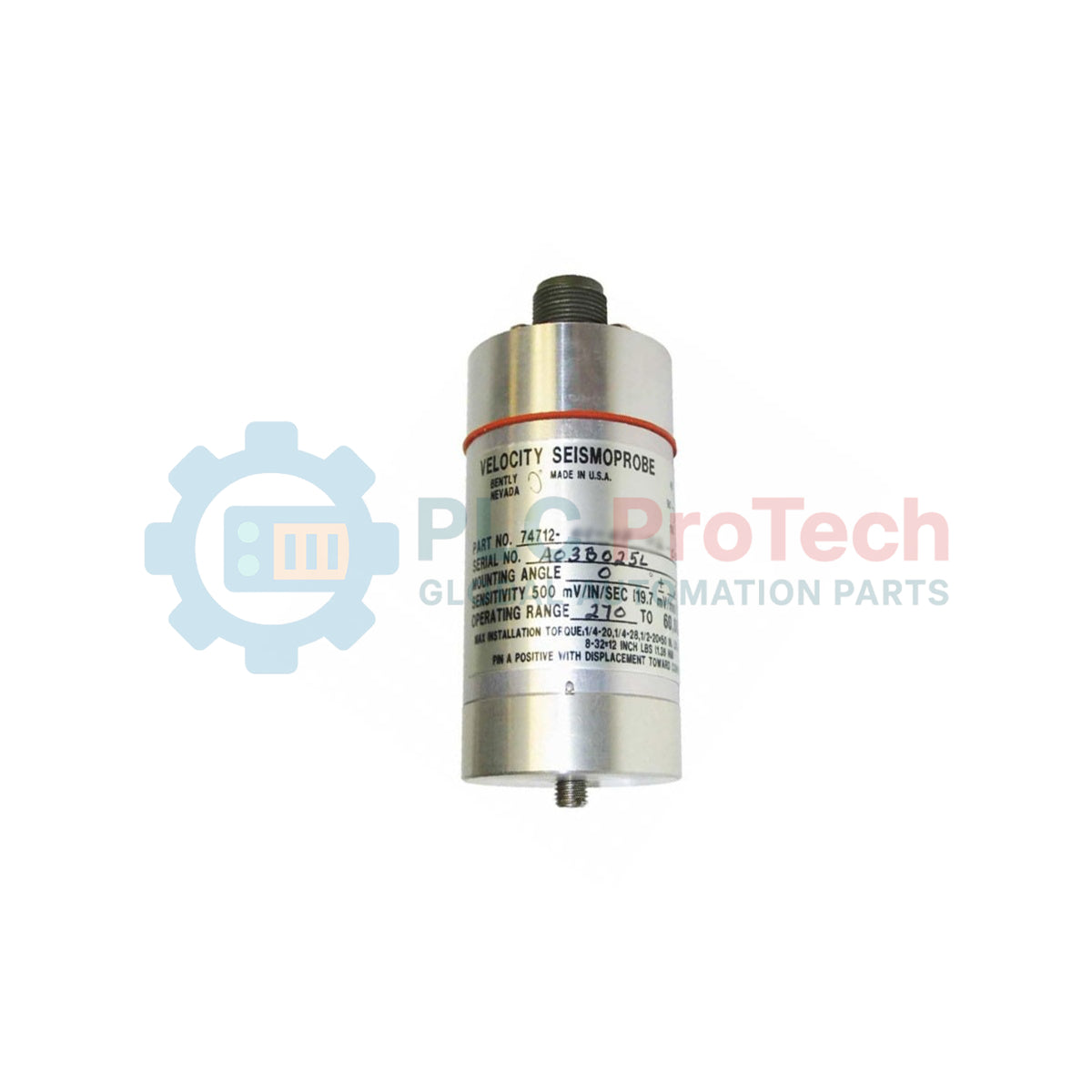
Designed for demanding high-temperature vibration monitoring environments, the Bently Nevada 74712-01-10-02-00 industrial velocity transducer provides critical machine casing measurements. This self-generating, two-wire sensor is specifically designed to measure structural velocity on gas turbines, steam turbines, or other high-temperature rotating machinery. Operating on an electrodynamic moving-coil design, the Bently Nevada 74712-01-10-02-00 provides a voltage output directly proportional to the vibration velocity, requiring no external power supply for signal generation.
Key Features
-
Self-Generating Design: Requires no external excitation power to generate the velocity voltage signal.
-
High Temperature Limit: Rated for sustained operation from -29 degC to +204 degC (-20 degF to +400 degF).
-
Optimized Mounting Angle: Configuration code 01 permits vertical mounting (0 +/-2.5 degrees) with a 4.5 Hz (270 cpm) minimum operating frequency.
-
Robust Connection: Top-mount connector housing protects signal wires from harsh environment exposure.
-
Secure Mounting Base: Features a circular M10X1 threaded connection base to ensure solid mechanical contact.
Industrial Applications
- Heavy industrial gas turbines and steam turbine casings.
- High-temperature power generation rotating assets.
- Process pumps, compressors, and exhaust fans in petro-chemical plants.
- Draft fans and machinery operating in extreme thermal zones.
Option Selection Decoding
| Option Code |
Parameter Description |
Selected Value |
| 01 |
Mounting Angle & Min Operating Frequency |
0 +/-2.5 degrees, 4.5 Hz (270 cpm) |
| 10 |
Mounting Base |
Circular M10X1 Thread |
| 02 |
Connector Orientation |
Top Mount |
| 00 |
Agency Approval |
No Approvals Standard |
Technical Specifications
| Specification |
Value / Detail |
| Manufacturer |
Bently Nevada |
| Model Number |
74712-01-10-02-00 |
| Transducer Type |
Electrodynamic Moving-Coil Velocity Transducer |
| Operating Temperature Range |
-29 degC to +204 degC (-20 degF to +400 degF) |
| Frequency Response Minimum |
4.5 Hz (270 cpm) |
| Mounting Configuration |
Vertical (0 +/-2.5 degrees) |
| Physical Height |
102 mm (4.0 in) typical |
| Physical Diameter |
41 mm (1.6 in) typical |
| Net Transducer Weight |
0.48 kg (1.06 lbs) |
| Shipping Weight (Calculated) |
2.0 kg (4.4 lbs) |
| Country of Origin |
United States (U.S.A.) |
Empirical Engineering Insights
Alternative Models & Compatibility
The 74712 velocity transducer series serves as a specialized, self-generating alternative to standard Piezoelectric Velocity Transducers (PVTs) in superheated environments where active electronics would fail. Ensure your monitor channel cards (such as the Bently Nevada 3500/42M) are explicitly configured to accept moving-coil (seismic) sensors. Attempting to run this on a standard accelerometer or IEPE channel configuration will produce signal clipping or no-reading errors.
Application Pitfalls & Engineering Notes
Never exceed the maximum structural temperature of 204 degC. Even though the body is designed for high temperatures, the interconnecting cabling must be insulated with FEP or glass braid. Avoid routing signal cabling along steam piping or unprotected thermal bridges without proper standoff brackets. Because this is a moving-coil sensor, physical drop damage can misalign the internal suspension springs, causing permanent sensitivity loss or signal distortion.
Commissioning & Wiring Tips
Always verify that the mounting surface is machined flat to at least 0.02 mm (0.001 inches) and free of rust or slag. Tighten the sensor to the specified torque. Avoid over-torqueing, which can warp the base and degrade the transducer frequency response. Ensure the shielding drain wire is only grounded at the system monitor panel; grounding both ends can induce ground loop noise into your turbine casing measurements.
Installation Guidelines
CRITICAL WARNING:
Ensure the machine is completely de-energized, depressurized, and cooled to ambient levels before performing installation. Direct contact with hot casing surfaces can cause severe personal injury. De-energize all power lines in the conduit route to prevent accidental electrical shock.
1
Inspect the machine casing mounting point. Ensure it matches the Circular M10X1 thread pattern and is drilled perpendicular to the casing surface to guarantee precise vertical alignment within the +/-2.5 degree specification limit.
2
Apply a light film of high-temperature mounting lubricant to the base threads and mate the transducer manually. Threading should be smooth. Torque the unit to the mechanical specification using a calibrated hand torque wrench.
3
Secure the high-temperature signal cable to the top mount connector. Ensure the cable is supported with adequate strain relief loops to prevent the weight of the conduit or cable bundle from stressing the connector housing.