Description
Engineered for high-performance motion control applications, the Delta Electronics ASD-A2-1021-U serves as a core drive component within the ASDA-A2 Series family. Delivering a rated output power of 1.0 kW under a 220V single-phase input configuration, this unit is specifically designed to meet the rigorous demands of modern industrial automation systems. By integrating advanced closed-loop control, a built-in electronic cam (E-Cam), and high-speed communication interfaces, it provides precise positioning, exceptional torque control, and smooth speed regulation for dynamic machine architectures.
Features
-
Advanced E-Cam Function: Built-in electronic cam with up to 720 points for smooth interpolative path planning and flying shear or rotary cut operations without external controller overhead.
-
Full-Closed Loop Control: Direct secondary encoder feedback interface to eliminate mechanical backlash and ensure endpoint positioning accuracy.
-
Suppression of Vibration: Dual-mode automatic high-frequency resonance suppression and low-frequency vibration damping filters for enhanced mechanical stability.
-
Versatile Extension Port: Designated "U" model configuration featuring high-speed extension ports for multiple expansion interfaces and communication options.
Applications
- Multi-axis CNC machining centers and high-speed precision milling setups.
- Flying shear, rotary cut, and packaging machinery requiring synchronized master-slave gearing.
- High-speed pick-and-place gantry robots and automated material handling lines.
- Textile, printing, and paper converting machines demanding continuous tension and registration control.
Technical Specifications
| Parameter |
Value / Specification |
| Manufacturer |
Delta Electronics |
| Model Number |
ASD-A2-1021-U |
| Series Name |
ASDA-A2 Series |
| Rated Output Power |
1.0 kW |
| Input Voltage / Phase |
220 VAC, 1-Phase / 3-Phase |
| Permissible Voltage Range |
170 to 255 VAC (50/60 Hz) |
| Control Modes |
Position, Speed, Torque, and Mixed Modes |
| Encoder Feedback Resolution |
20-bit incremental / absolute (1,280,000 p/rev) |
| Built-in Dynamic Brake |
Integrated |
| Cooling Method |
Natural convection / Forced fan cooling |
| Net Weight |
2.0 kg |
| Shipping Weight (Calculated) |
4.0 kg |
Connections and Interfaces
| Connector / Terminal |
Functional Assignment |
| L1, L2, L3 (R, S, T) |
Main AC Power Input Terminals (Use L1/L2 for single-phase operation) |
| U, V, W |
Servo Motor Output Terminals (Do not connect to AC line power) |
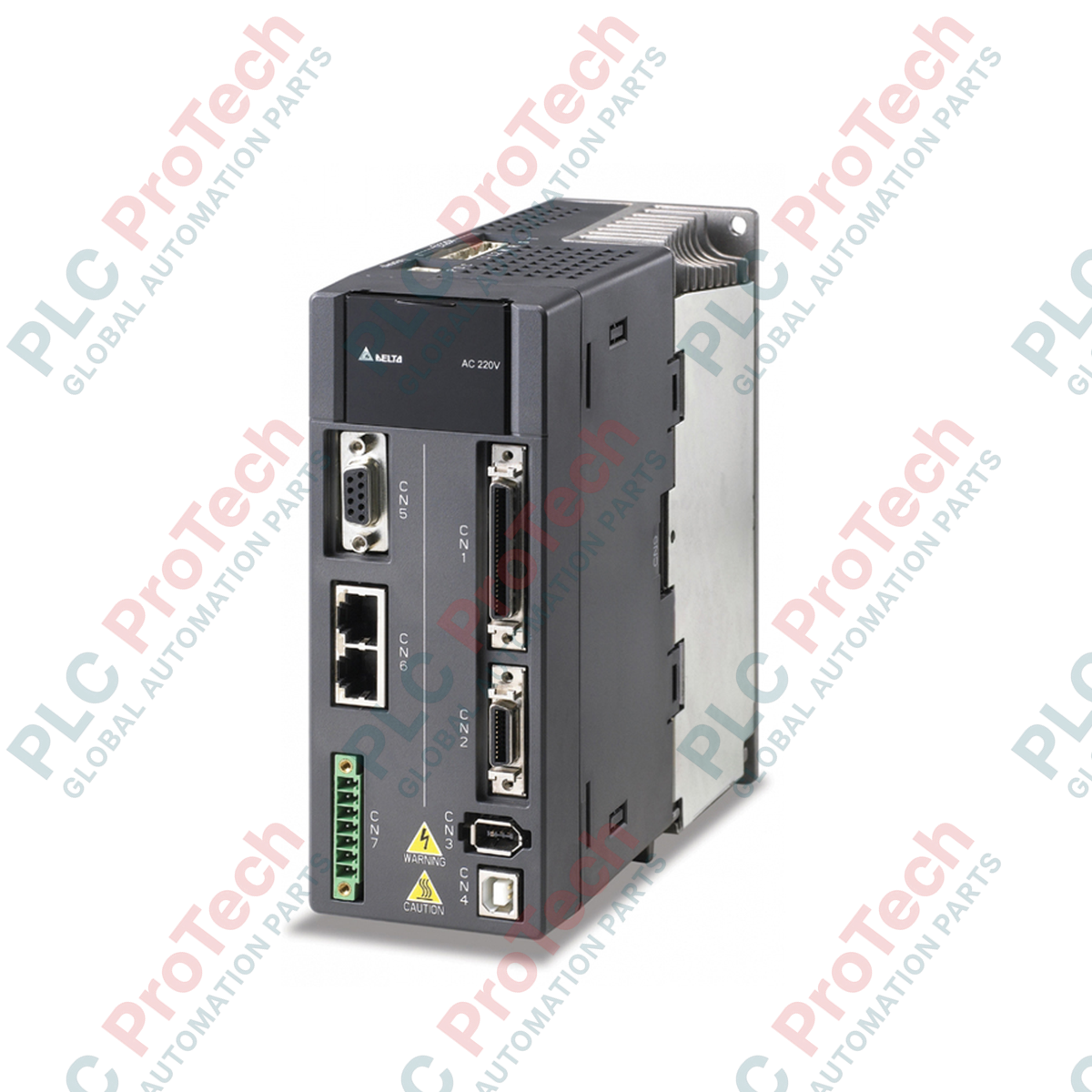
| CN1 |
Control I/O Interface (50-pin MDR connector for digital/analog inputs & outputs) |
| CN2 |
Motor Encoder Interface (Feedback signal reception from the motor) |
| CN3 |
Communication Interface (USB / RS-485 / RS-232 connections for software setup) |
| CN4 |
Full-Closed Loop Interface (Auxiliary encoder input for linear scale feedback) |
Empirical Engineering Insights
Alternative Models & Compatibility
The ASDA-A2 model variants with the "-U" suffix are functionally compatible with standard "B" or "M" models in analog torque and speed modes, but differ significantly in their digital bus capabilities and the physical full-closed loop CN4 feedback layout. When upgrading from older ASDA-AB series drives, please note that the control cabinet layout requires adjustments, as the footprint is not identical, and physical encoder cables must be upgraded to support the 20-bit serial encoder standard of the A2 motor series.
Application Pitfalls & Engineering Notes
When operating the ASD-A2-1021-U drive on single-phase 220 VAC power instead of a three-phase supply, the internal DC bus voltage ripple increases during high-acceleration/deceleration cycles. Under these conditions, avoid driving the motor continuous-duty cycles exceeding 80% of rated torque. If high inertia loads are present, the internal regeneration capability may trigger a AL005 (Overvoltage) fault. This must be resolved by calculating the regeneration energy and adding an external braking resistor across terminals P+ and D, while adjusting parameter P1-52 to match the resistance and power rating of the external component.
Commissioning & Wiring Tips
To prevent electrical noise issues with high-resolution 20-bit encoders, ensure the motor frame is grounded directly to the drive’s PE terminal using minimum 14 AWG wire. When utilizing the CN1 interface for pulse train positioning, always use twisted-pair shielded cables with the shield terminated at the drive chassis end only. Ensure that parameters P2-15 through P2-17 (Digital Input Filters) are correctly configured to match the input signal frequency to filter out signal bounce or external high-frequency EMI.
Installation Guidelines
CRITICAL WARNING: Before installing, removing, or wiring the drive, ensure that the main power source is completely disconnected. Wait at least 10 minutes after turning off the power to allow the internal high-voltage DC bus capacitors to discharge to a safe level (below 50V). Measure the voltage between terminals P+ and N- with a reliable multimeter to confirm the zero-energy state before proceeding.
1
Mount the drive vertically inside a clean, dry, IP54-rated metal enclosure. Ensure a minimum clearance of 50 mm above and below, and 10 mm on either side of the drive chassis to permit adequate convective airflow from the integrated cooling fans.
2
Connect the main single-phase AC incoming power lines to terminals L1 and L2. Leave L3 open. Ensure a properly sized branch-circuit fuse or molded case circuit breaker (MCCB) is installed upstream for thermal overload protection.
3
Wire the servo motor output terminals U, V, and W directly to the corresponding motor phase leads. Under no circumstances should AC mains supply power be connected directly to U, V, and W, as this will result in immediate, catastrophic damage to the drive output stage.
4
Verify that the ground terminal of the drive is connected to the common system ground bar using the shortest possible path, utilizing a heavy-gauge copper grounding conductor to minimize electromagnetic interference.