Systemprofil & Betriebssicherheit
Die DS215TCEAG1BZZ01A fungiert als die definitive hardwareseitige Schutzbarriere innerhalb der Mark V Speedtronic Turbinensteuerungsarchitektur von General Electric. Direkt im dedizierten Schutz-Core (als Core bezeichnet) installiert, führt dieses sicherheitskritische Modul Echtzeitdiagnosen bei Not-Überschwingbedingungen und kritischen Flammenüberwachungsparametern durch. Grundlast-Wärmekraftwerke, große petrochemische Raffinerien und isolierte mechanische Antriebsanlagen setzen die DS215TCEAG1BZZ01A (DS215TCEAG1BZZ01A) ein, um Not-Auslöseschleifen unabhängig von den primären Steuerprozessoren zu steuern. Durch die Verarbeitung von Rohimpulsen der Drehzahlsensoren und die Berechnung von Auslösegrenzen mittels dedizierter Onboard-Hardwarelogik reagiert diese Karte sofort bei Turbinenüberdrehzahl, um hydraulische Auslöseköpfe abzuschalten. Diese Reaktion im Sub-Millisekundenbereich vermeidet katastrophale mechanische Belastungen, verhindert kritische Wellenbeschädigungen und erhält die Anlageninfrastruktur, während sie langfristige Wartungsausfälle reduziert.
Hardware-Topographie & Core-Routing
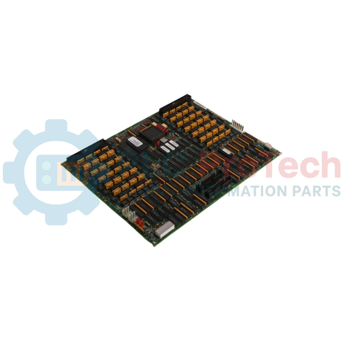
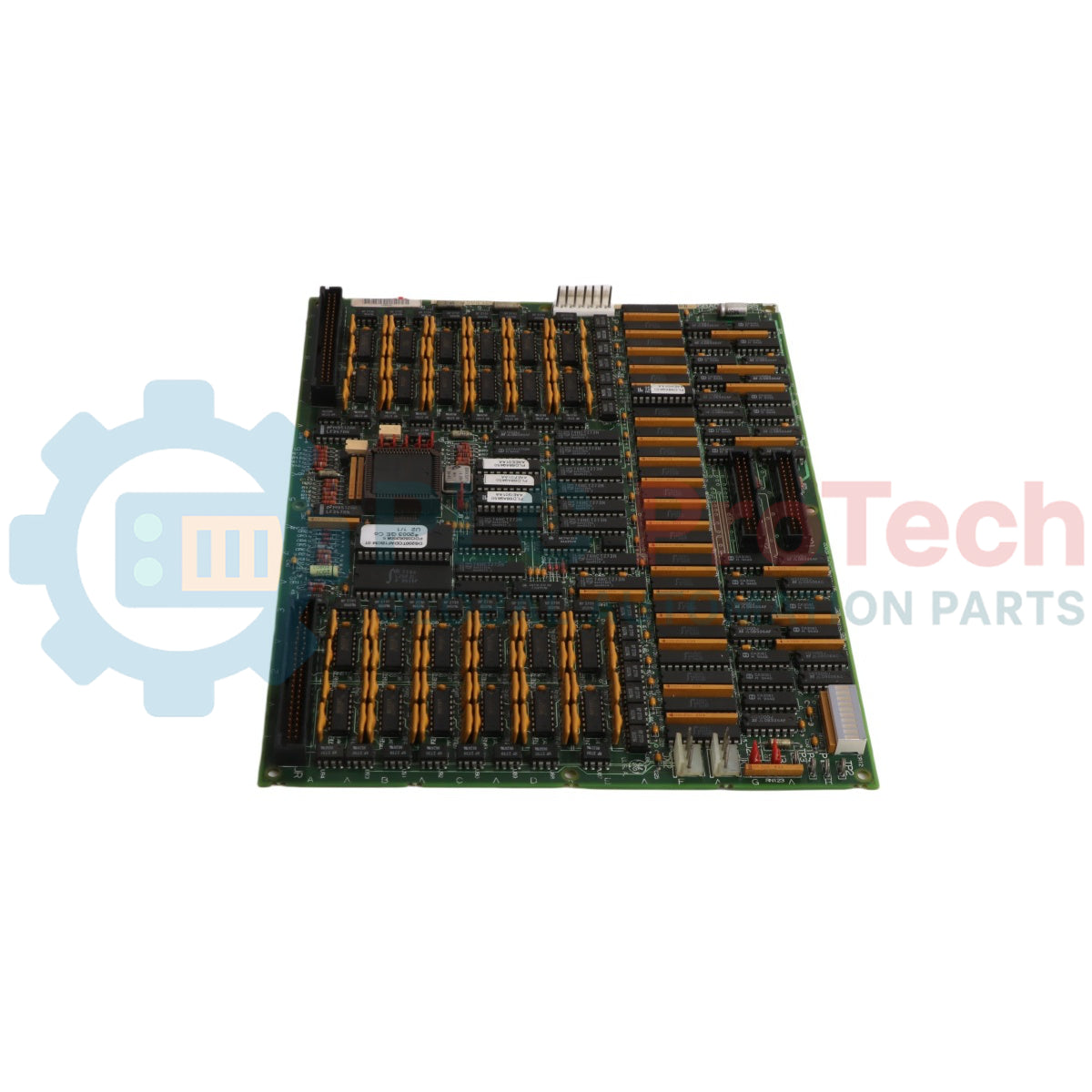
Die Strukturarchitektur der DS215TCEAG1BZZ01A Schutzplatine nutzt unabhängige Verarbeitungsblöcke und hochdichte Schnittstellenknoten.
-
Isolierter Schutzprozessor: Beherbergt einen leistungsstarken Onboard-Mikroprozessor, der deterministische Sicherheitsroutinen ausführt, gespeist von Firmware, die in sockelbaren, herausnehmbaren löschbaren programmierbaren Nur-Lese-Speicherblöcken (EPROM) gespeichert ist.
-
Flammensensor-Hochspannungsversorgung: Integriert einen spezialisierten Hochspannungskreis über den JW-Stecker, der bis zu 335 VDC zur Versorgung externer Flammenverfolgungsfelder bereitstellen kann.
-
Multipunkt-Hardwareprogrammierung: Verfügt über ein Array von 30 physischen Hardware-Berg-Steckbrücken zur manuellen Codierung der genauen Betriebssteckplatzposition und der Abstimmungslogik innerhalb des Cores.
-
Duale Bus-Kommunikation: Integriert JX1- und JX2-verkettete IONET-Verbindungssockel zur Übertragung von Hintergrunddiagnoseergebnissen und Auslösezustandsdaten über hochzuverlässige Kommunikationsverbindungen.
System-Spezifikationen & Parameter
| Ingenieurmetrisch |
Technische Bewertung |
| Modellnummer |
DS215TCEAG1BZZ01A (austauschbar mit DS200TCEAG1BZZ01A) |
| Markenhersteller |
General Electric (GE-Platinen & Turbinensteuerung) |
| Steuerungsserie |
Speedtronic Mark V (DS200 Serie) |
| Funktionales Akronym |
TCEA-Karte |
| Core-Montagezone |
Core (Schutzschnittstellenmodul) |
| Onboard-Verarbeitungseinheit |
Ein einzelner dedizierter Hochgeschwindigkeits-Mikroprozessor |
| Instruktionsspeicher |
Werkseitig programmierte, herausnehmbare EPROM-Module |
| Onboard-Schutz |
3 Hochleistungs-Sicherungen |
| Hardware-Konfigurationsarray |
30 einzelne Berg-Steckbrücken |
| Flammenüberwachungsausgang |
335 VDC Ausgang über JW-Stecker |
| Intermodulare Kommunikation |
JX1- und JX2-Reihengeschaltete IONET-Steckverbinder |
| Signalträgerverbindung |
JK-Stecker (Schnittstelle zur TCEB-Karte) |
| Auslöseaktionsverbindung |
JL-Ausgangsstecker |
| Unterflächenschutz |
Normale PCB-Konformbeschichtung |
| Betriebstemperaturbereich |
0 bis 60 °C |
| Herkunftsland |
Vereinigte Staaten |
FAQs zur Sicherheitskreisdianostik
Welche spezifische Rolle spielt der DS215TCEAG1BZZ01A während der Zündphase und wie erfolgt die Schnittstelle zur Flammenverfolgung?
Die Platine regelt und liefert eine kontinuierliche 335 VDC-Vorspannung über den JW-Stecker an die feldmontierten Flammendetektoren. Sie liest die zurückkehrenden niederpegeligen Flammenionisationssignale, verarbeitet den Zündzustand und stellt bei einem Flammenausfall während des kritischen Turbinenbetriebs sofortige Notabschaltlogik bereit.
Wie erkennt eine Ersatzplatine ihre zugewiesene Position innerhalb des Schutzkerns?
Die Hardware-Position und Anwendungsvariablen werden durch die Konfiguration der 30 onboard Berg-Stecker bestimmt. Beim Vorbereiten einer neuen Karte müssen Ingenieure das Muster dieser Jumper physisch mit den Positionen der Originalkarte abgleichen, um eine korrekte Schnittstelle mit der Kernlogik sicherzustellen.
Wie lautet das korrekte Austauschprotokoll, wenn die onboard EPROM-Daten beschädigt sind?
Tritt ein Firmware-Fehler auf, können die vorhandenen EPROMs aus ihren Sockeln entfernt und durch neue, werkseitig geprüfte Firmware-Module ersetzt werden. Da diese Chips sehr empfindlich gegenüber elektrostatischer Beschädigung sind, muss dieses Verfahren stets unter vollständigen ESD-Statik-Erdungsprotokollen durchgeführt werden, um die internen Speicherarrays zu schützen.
Feldtechnik & Installationsprotokoll
-
Maßnahmen zur statischen Entladung zum Schutz der EPROMs:
Die onboard EPROM-Module und die Mikroprozessor-Logik sind anfällig für dauerhafte Schäden durch elektrostatische Entladung. Feldtechniker müssen vor dem Auspacken oder Berühren der Platine ein geerdetes ESD-Armband tragen. Stellen Sie sicher, dass die Erdungsklammer fest mit einem unlackierten, geerdeten Metallrahmen oder Werkbank verbunden ist, um einen klaren statischen Entladungsweg von den Bauteilen weg zu gewährleisten.
-
Überstrom-Sicherung: Prüfung und Austausch:
Die Platine verfügt über 3 dedizierte Schutzsicherungen, um interne Unterkreise vor Kurzschlüssen in der externen Feldverdrahtung zu isolieren. Vor der Inbetriebnahme einer neuen oder reparierten Platine ist die Durchgängigkeit und der korrekte Nennstrom dieser Sicherungen zu überprüfen. Ist eine Sicherung durchgebrannt, sollte der externe 335 VDC-Flammenkreis oder der J7-Stromverteilungsstecker vor dem Neustart des Systems überprüft werden.
-
Richtlinien für die Reihenschaltung von IONET-Abschlüssen:
Beim Verbinden der JX1- und JX2-IONET-Steckverbinder über mehrere Module im Rack hinweg ist darauf zu achten, dass die Abschlusswiderstände am Ende des Datenbusses korrekt platziert sind. Unsachgemäß geschlossene Reihenschaltungen erzeugen hochfrequente Signalreflexionen im IONET-Netzwerk, die zu Kommunikationszeitüberschreitungen zwischen dem Schutzmodul und dem primären Master-Controller führen können.