Description
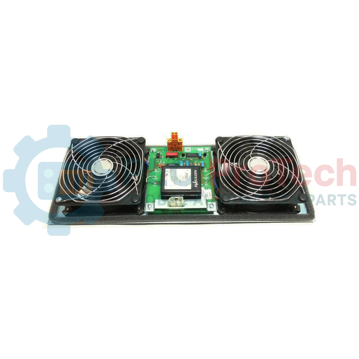
Designed to maintain thermal equilibrium within critical system enclosures, the Honeywell 51199947-175 represents a high-reliability forced-convection cooling solution engineered specifically for industrial control cabinets. This robust assembly integrates an active failure-monitoring circuit that interfaces directly with central supervisory control systems to ensure immediate warning upon fan deceleration or failure. Operating on a wide-range input voltage of 85-132V AC at 47-63 Hz, the assembly provides steady, high-volume airflow to mitigate heat buildup in high-density DCS and PLC cabinets, protecting sensitive electronic components from thermal degradation.
Key Features
-
Integrated Alarm Monitoring: Dedicated hardware contact switch triggers an alarm state during motor stall or power failure conditions.
-
Wide Input Voltage Tolerance: Engineered to withstand voltage fluctuations from 85V to 132V AC without compromising fan speed or airflow dynamics.
-
Industrial-Grade Bearing System: Designed for continuous 24/7 duty cycle operations in high-ambient control room environments.
-
Durable Frame Construction: Rugged mounting chassis allows for direct installation into standard industrial cabinet racking configurations.
Applications
- Honeywell TDC 3000 and Experion PKS system cabinet thermal management.
- Main power supply and system controller cabinet active ventilation.
- Harsh industrial environments requiring positive pressure cooling and active system-level diagnostic feedback.
Technical Specifications
| Parameter |
Specification Values |
| Manufacturer |
Honeywell |
| Model Number |
51199947-175 |
| Rated Operating Voltage |
85 to 132V AC |
| Rated Line Frequency |
47 to 63 Hz |
| Rated Current Consumption |
0.5A AC |
| Alarm Contact Rating |
0.5 Amp Max DC / Peak AC Resistive |
| Alarm Switch Voltage Limit |
200 VDC Peak |
| Net Unit Weight |
3.22 kg |
| Shipping Weight (Calculated) |
4.50 kg |
Connections and Interfaces
| Terminal Connection |
Signal / Circuit Assignment |
| L / N / PE |
AC Input Supply Mains (Line, Neutral, Protective Earth) |
| Alarm Switch Contact 1 |
Common Alarm Contact Return |
| Alarm Switch Contact 2 |
Active Alarm Output (Triggers open/close circuit upon speed loss) |
Empirical Engineering Insights
Alternative Models & Compatibility
The 51199947-175 acts as a direct-fit replacement for older, non-alarm-monitored fan assemblies used in Honeywell legacy cabinet frameworks. When upgrading older cabinets to this monitored variant, ensure the digital input card configuration on the Honeywell node (e.g., HLAI or DI modules) is correctly mapped to recognize the dry contact switch state change.
Application Pitfalls & Engineering Notes
Avoid using this assembly in environments where corrosive gases are highly concentrated without appropriate pre-filtration. While the fan motor housing is sealed, dust buildup on the alarm sensor rotor can trigger premature failure alarms even when the fan continues to rotate at nominal RPM. Ensure regular filter panel changes to maximize lifespan.
Commissioning & Wiring Tips
To prevent electrical noise coupling from the AC fan motor into high-sensitivity DCS analog circuits, isolate the alarm contact feedback wires. Run the dual alarm contacts through a shielded twisted pair (STP) cable directly back to the auxiliary terminal panel, grounding the shield strictly on the controller side.
Installation Guidelines
CRITICAL WARNING: Hazardous voltage levels are present within the cabinet terminal blocks. De-energize and lock out all AC incoming power lines before initiating physical mounting or wire terminations. Verify the absence of voltage with a calibrated instrument prior to beginning work.
1
Position the assembly inside the cabinet fan slot, aligning the chassis holes with the standard rack mounting threads. Secure the fan using the designated vibration-damping hardware.
2
Connect the protective earth wire to the PE terminal block to ensure proper electrical fault grounding before connecting the live and neutral AC lines.
3
Terminate the dry-contact alarm output lines to your system's digital input module. Verify correct terminal torque parameters to prevent high-resistance contacts.