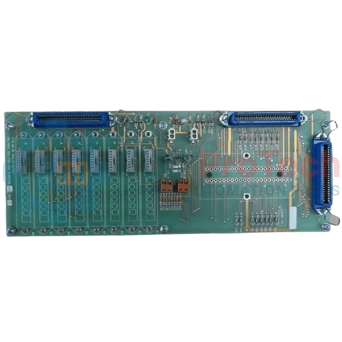
Description
Providing critical electrical isolation for analog output control loops in process environments, the Honeywell 51304638-600 serves as a high-reliability Rev F Analog Output Galvanic Isolator. This instrument grade module is engineered to interrupt ground loops, block transient electrical surges, and ensure precise signal transmission between host DCS controllers and field-mounted control elements such as control valves, actuators, and positioners. By employing magnetic or optical galvanic separation, it safeguards sensitive control room electronics from field-side faults and electromagnetic interference (EMI).
Features
-
Galvanic Isolation: Provides robust isolation barrier preventing ground potential loops between control systems and field equipment.
-
Revision F Optimization: Upgraded thermal profiles and high-reliability solid-state components for extended service life.
-
Low Signal Distortion: Delivers high-linearity analog signal reproduction, maintaining calibration integrity from input to output.
-
System Integration: Designed specifically for seamless mounting on Honeywell Field Termination Assemblies (FTAs).
-
Passive Control Loop Support: Optimized for standard 4-20mA current loop configurations.
Applications
- Petrochemical and oil refining process control systems.
- Intrinsic safety barriers in hazardous area instrumentation loops.
- Power generation and turbine control auxiliary systems.
- Water and wastewater treatment distribution loops.
Technical Specifications
| Parameter |
Value / Specification |
| Manufacturer |
Honeywell |
| Model Number |
51304638-600 |
| Hardware Revision |
Rev F |
| Device Type |
Analog Output Galvanic Isolator |
| Signal Range |
4-20 mA DC |
| Supported Systems |
Honeywell TDC 3000 / TPS / Experion Series |
| Isolation Mechanism |
Galvanic barrier separation |
| Shipping Weight (Calculated) |
3.0 kg |
| Package Dimensions (Calculated) |
25.0 cm x 18.0 cm x 10.0 cm |
Empirical Engineering Insights
Alternative Models & Compatibility
The 51304638-600 Rev F is fully backward compatible with older Revision D and Revision E variants of the same part family. When swapping modules on older TDC 3000 Field Termination Assemblies (FTAs), confirm that the active channel slots are clean and that existing pin alignments have not suffered mechanical fatigue over years of service.
Application Pitfalls & Engineering Notes
In enclosed cabinet installations with dense multi-channel configurations, thermal buildup can affect passive isolation channels. Maintain adequate airflow across the cabinet housing to prevent temperature-induced current calibration drift. Ensure that external loop resistance does not exceed the maximum driven load capacity specified by the host analog output controller card feeding the isolator.
Commissioning & Wiring Tips
Always verify signal polarity before connecting the field loops. Reverse polarity will not damage the module due to integrated protection circuits, but it will interrupt loop operations and report an open-circuit fault on the host controller. Use twisted, shielded pair wiring for all output connections, grounding the shield exclusively at the system control cabinet end.
Installation Guidelines
CRITICAL WARNING:
De-energize all power sources to both the system carrier/backplane and the field instrument loops before attempting insertion or extraction of the module. Failure to follow proper safety and static-discharge protocols can lead to control card failure or transient disruptions in live loop signals.
1
Ensure you are grounded using a calibrated ESD wrist strap attached to a verified system ground point.
2
Visually inspect the module edge connectors and physical mating pins for dust, corrosion, or physical misalignment.
3
Align the module carefully in the dedicated slot on the Field Termination Assembly (FTA) and apply firm, even pressure until the card is fully seated.
4
Re-verify the loop wiring sequence, energize the circuit, and perform a loop check at 4mA and 20mA to confirm loop calibration.