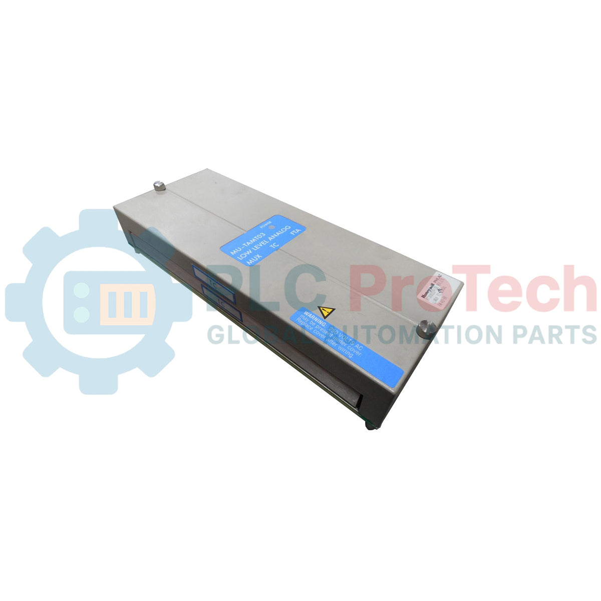
Description
Routing and conditioning low-level analog field signals within the Honeywell TDC 3000 control architecture, the Honeywell MU-TAMT03 functions as a dedicated Low Level Analog Multiplexer Module optimized for high-density thermocouple and RTD thermal monitoring. This module acts as the vital bridge between low-voltage field sensors and the high-performance process managers, reducing overall field wiring complexity by multiplexing input signals directly at the I/O rack level. Designed for continuous industrial duty, the MU-TAMT03 guarantees high signal integrity and robust protection against common-mode noise in highly electromagnetic industrial environments.
Features
- High-density multiplexing of microvolt-level inputs, minimizing control system footprint and interface hardware requirements.
- Direct integration with Honeywell High-Performance Process Manager (HPM) and APM card file slots.
- Exceptional noise rejection and signal filtering, safeguarding low-level measurements from high-frequency industrial EMI.
- Seamless operation with compatible Field Termination Assemblies (FTAs) for secure field wiring termination.
- Ruggedized component architecture engineered for long-term reliability in non-condensing industrial environments.
Applications
- Continuous temperature profiling in chemical reactor vessels and distillation columns.
- Multi-point thermocouple logging in industrial cracking units and furnace installations.
- High-accuracy cold-junction referenced thermal monitoring systems in power generation facilities.
- Critical machinery bearing temperature tracking.
Technical Specifications
| Parameter |
Value |
| Manufacturer |
Honeywell |
| Model Number |
MU-TAMT03 |
| Control Series |
TDC 3000 / Experion TPS |
| Module Type |
Low Level Analog Multiplexer Module (LLMUX) |
| Compatible FTAs |
MC-TAMT03 / MC-TAMT13 Series |
| Input Formats |
Thermocouple (TC), RTD, Low-Voltage Millivolt (mV) |
| Operating Temperature |
0 to 60 degC |
| Storage Temperature |
-40 to 85 degC |
| Relative Humidity |
5% to 95% RH (Non-condensing) |
| Country of Origin |
USA |
| Shipping Weight (Calculated) |
1.5 kg |
| Package Dimensions (Calculated) |
28.0 x 14.0 x 8.0 cm |
Alternative Models & Compatibility
The MU-TAMT03 directly replaces legacy MU-TAMT01 and MU-TAMT02 hardware revisions, offering improved thermal drift performance and higher resistance to signal attenuation. When performing upgrades, verify that the existing card file backplane version and the IOP (Input/Output Processor) software parameters are aligned to support the -TAMT03 hardware profile.
Application Pitfalls & Engineering Notes
Because thermocouple and low-voltage millivolt signals operate on microvolt thresholds, they are exceptionally susceptible to external electrical noise. Ensure that signal cables are routed through dedicated, grounded conduits away from high-power AC lines or variable frequency drives (VFDs) to prevent cross-talk and channel calculation errors on the multiplexer. Maintain adequate cabinet ventilation to prevent heat build-up which can distort built-in cold-junction measurements.
Commissioning & Wiring Tips
Always terminate sensor shield wires at the designated Field Termination Assembly (FTA) ground bus rather than at the module end to eliminate ground loop current paths. During commissioning, perform a channel-by-channel calibration check using a certified mV simulator to verify the integrity of the cold junction compensation circuit before finalizing control loop configurations in the TDC 3000 database.
Installation Guidelines
CRITICAL WARNING
Isolate all electrical power sources servicing the card file and connected field loops prior to module insertion or extraction. Hot-plugging this card when surrounding field wiring is energized can result in backplane damage or cause transient noise spikes that disrupt active process control nodes.
1
Power down the corresponding TDC 3000 I/O card slot or rack segment prior to physical card handling.
2
Align the MU-TAMT03 module with the plastic guides in the designated card file slot.
3
Slide the module firmly until the rear connector completely seats into the backplane, then lock the securing tabs.