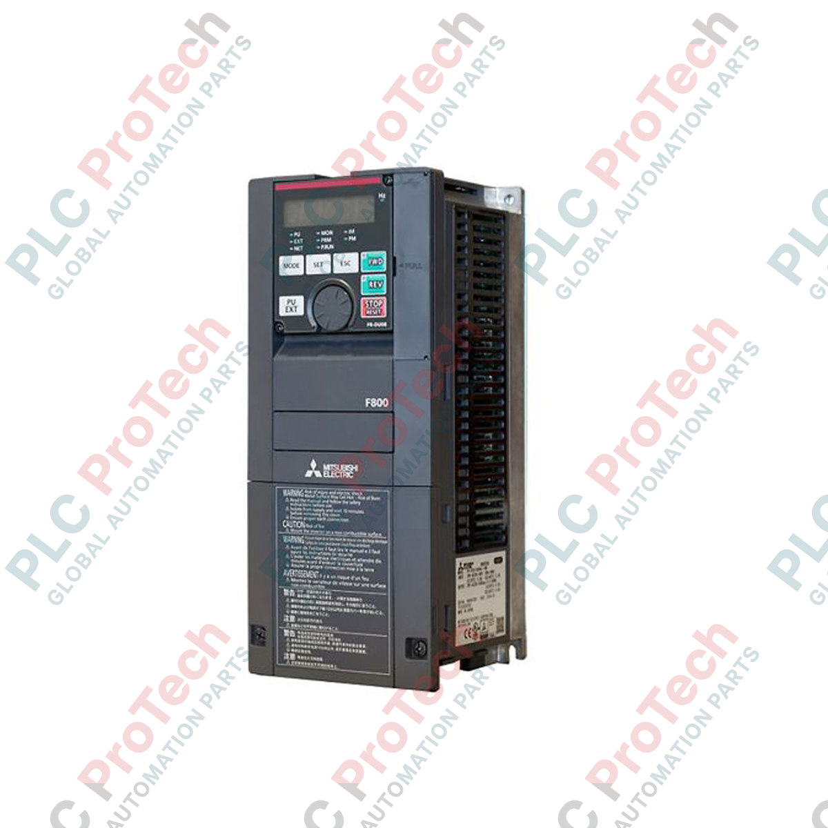
Description
Regulating system dynamics with exceptional efficiency, the Mitsubishi Electric FR-F840-00170-2-60 is a dedicated variable frequency drive engineered primarily for pump, fan, and compressor operations. This FR-F800 Series controller provides precise speed regulation over three-phase AC motors, featuring dual overload ratings to optimize physical sizing and thermal margins. By utilizing advanced energy-saving algorithms, the drive dynamically adjusts excitation current in response to load fluctuations, maximizing operational efficiency under real-time conditions. The robust IP20 enclosure is designed for standardized panel mounting within industrial environments, incorporating integrated PID control loops to streamline system architectures without requiring external controllers.
Features
-
Dual Rating Modes: Features Super Light Duty (SLD) and Light Duty (LD) ratings to align precisely with specific torque applications.
-
Optimum Excitation Control: Automatically calculates and applies the ideal magnetic flux matching the load, minimizing thermal losses.
-
Built-In PID Controller: Allows direct process loop management for flow, pressure, or temperature regulation without PLC intervention.
-
Enhanced Safety Integration: Equipped with safety stop functions complying with global machinery protection requirements.
-
Integrated USB Port: Facilitates direct connection to engineering software for diagnostic plotting and parameter backups.
Applications
-
Fluid Management: Municipal and industrial water pump control, including booster systems and dry-run protection.
-
HVAC Systems: Intake, exhaust, and recirculation air-handling fans in commercial or industrial facilities.
-
Compressor Control: Dynamic speed control for positive-displacement and centrifugal air compression units.
Technical Specifications Table
| Parameter |
Specification value |
| Manufacturer |
Mitsubishi Electric |
| Model Code |
FR-F840-00170-2-60 |
| Series |
FR-F800 |
| Power Rating |
7.5 kW |
| Supply Voltage |
380 to 500 V AC (3-Phase) |
| Rated Current (SLD) |
17.0 A |
| Rated Current (LD) |
16.0 A |
| Operating Temperature (SLD) |
-10 to +40 degC |
| Operating Temperature (LD) |
-10 to +50 degC |
| Ingress Protection Rating |
IP20 |
| Shipping Weight (Calculated) |
7.5 kg |
Connections and Interfaces
| Terminal Group |
Function / Circuit Assignment |
| R/L1, S/L2, T/L3 |
Three-phase AC main power supply inputs. |
| U, V, W |
Three-phase AC variable frequency outputs to motor. |
| STF / STR |
Forward rotation start / Reverse rotation start control lines. |
| 10, 2, 5 |
Analog input terminals for external speed setting (0 to 10 V DC). |
| SD, SE |
Common terminals for digital inputs and open collector outputs. |
Empirical Engineering Insights
Alternative Models & Compatibility
This unit directly succeeds legacy FR-F740 models. When transitioning, verify the operational parameter logic because terminal assignments match, but software parameters (especially those referencing motor constants and auto-tuning) require translation using FR Configurator2. Parameter conversion utilities within the software automate this migration but necessitate validation prior to line commissioning.
Application Pitfalls & Engineering Notes
When sizing for high-altitude operations, derate current output by 1% for every 100 meters above 1000 meters up to a maximum of 2500 meters. For applications involving high-inertia loads like large extraction fans, integrate an external braking resistor to prevent overvoltage trips (E.OV3) during deceleration phases, especially when rapid deceleration cycles are scheduled.
Commissioning & Wiring Tips
Ensure the control signal wiring is completely segregated from the primary motor and input power cables. Use shielded twisted-pair (STP) wiring for analog speed references (terminals 2 and 5) and tie the shield exclusively to terminal 5 on the drive side to eliminate ground loops. In noisy electromagnetic environments, installing a zero-phase reactor on the input line significantly mitigates EMI issues.
Installation Guidelines
CRITICAL WARNING: Hazardous voltages remain present on the internal DC bus capacitors even after the AC line power has been isolated. Wait a minimum of 10 minutes after disconnecting input power, and verify with a multimeter that the DC bus voltage across terminals P/+ and N/- is below 45 V DC before performing any electrical connection or inspection work.
1
Mount the inverter vertically on a flat, non-flammable surface inside an enclosure that maintains ambient temperatures within the operational thresholds (-10 to +50 degC for Light Duty setups).
2
Ensure minimum clearances of 50 mm above and below the drive and 20 mm on the sides to facilitate unhindered convection cooling.
3
Connect the protective earth (PE) terminal first, utilizing a low-impedance grounding cable to mitigate common-mode noise issues.