Description
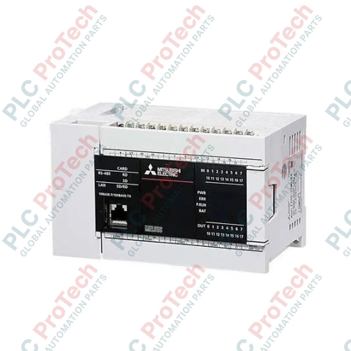
Execution of high-speed industrial control tasks is central to the Mitsubishi Electric FX5U-32MT/DS, a compact PLC CPU module belonging to the MELSEC iQ-F series. Designed to handle demanding automation requirements, this main unit integrates a high-speed execution engine with onboard analog capabilities and versatile communication interfaces. Utilizing a 24 V DC power supply, it coordinates up to 32 local I/O points directly on the chassis, functioning as the primary controller for distributed processing nodes, material handling systems, and complex assembly machinery.
Features
-
Onboard Processing Power: High-speed program execution handling basic instructions at 34 ns, optimizing machinery cycle times.
-
Integrated Communication: Built-in Ethernet port for network integration and an RS-485 port for multi-drop serial control.
-
Analog Performance: Built-in 2-channel analog input and 1-channel analog output (0 to 10 V DC) for immediate sensor and drive interfacing.
-
SD Card Slot: Supports standardized SD/SDHC cards for comprehensive data logging, firmware updates, and program backups.
-
Advanced Positioning: Features 4-axis pulse output (200 kpps) for precise stepper or servo motor control.
Applications
- Multi-axis positioning systems in automated assembly lines.
- Embedded machine control for packaging and labeling equipment.
- Pumping, HVAC, and environmental control systems utilizing built-in PID loops.
- Remote monitoring and telemetry systems using integrated Modbus/TCP or SLMP communications.
Technical Specifications
| Parameter |
Specification |
| Manufacturer |
Mitsubishi Electric |
| Model Code |
FX5U-32MT/DS |
| Power Supply Voltage |
24 V DC (+20%, -15%) |
| Total Onboard I/O |
32 points |
| Input Points |
16 points (24 V DC, Sink/Source) |
| Output Points |
16 points (Transistor, Sink) |
| 5 V DC Internal Supply Capacity |
900 mA |
| 24 V DC Internal Supply Capacity |
480 mA |
| Program Memory Capacity |
64k steps (Flash memory) |
| Onboard Ethernet Port |
1 port (RJ45, 100BASE-TX/10BASE-T) |
| Onboard Serial Port |
1 port (RS-485, terminal block) |
| Operating Temperature Range |
-20 to 55 degC (non-freezing) |
| Country of Origin |
Japan |
| Shipping Weight (Calculated) |
0.65 kg |
| Package Dimensions (Calculated) |
150 mm x 120 mm x 110 mm |
Connections and Interfaces
| Terminal / Port |
Function / Assignment |
| L / N (or +, -) |
Power supply connection: 24 V DC input |
| X0 to X17 |
Digital Inputs (Sink/Source selectable via S/S terminal) |
| Y0 to Y17 |
Transistor Outputs (Sink configuration, common terminals) |
| V+ / CH1 / CH2 |
Built-in analog input channels (0-10 V DC) |
| V+ / DA |
Built-in analog output channel (0-10 V DC) |
| SG / SDA / SDB / RDA / RDB |
Built-in RS-485 communication terminal block |
Alternative Models & Compatibility
When migrating legacy systems from the FX3U series (e.g., FX3U-32MT/DS) to the FX5U architecture, note that the physical terminal blocks and mounting footprint may differ slightly. Programming libraries must be compiled in GX Works3, as older GX Works2 projects are not directly executable without a hardware conversion procedure. Ensure that peripheral expansion modules are updated to the compatible FX5-series extension units, as older FX3 expansion blocks require an bus conversion module (FX5-CNV-BUS).
Application Pitfalls & Engineering Notes
The transistor outputs (Y0 to Y17) on this module are designed strictly for sink operations. Attempting to wire inductive loads without external flyback or suppression diodes will degrade the internal output transistors, potentially causing them to fail in a short-circuited state. Additionally, when using the 24 V DC service power supply to power external sensors, ensure the total current draw does not exceed 480 mA to prevent thermal shutdown of the CPU module.
Commissioning & Wiring Tips
To minimize high-frequency noise interference on the integrated analog input channels, route analog signal cabling in shielded twisted pairs separated from high-voltage motor or power cables by at least 100 mm. Ground the cable shield at a single point on the control panel's main grounding plate. When configuring the RS-485 network, enable the terminal resistor switch on the side of the FX5U module if it resides at either physical end of the communication trunk.
Installation Guidelines
CRITICAL WARNING: Prior to attempting physical installation, wiring, or maintenance on the CPU, ensure that all external power supplies (main control and field I/O voltages) are completely de-energized. Verify the absence of voltage on all terminal points using a calibrated multimeter. Failure to isolate power can result in terminal arcing, equipment damage, or severe electrical shock.
1
Mount the PLC main unit onto a clean, flat 35 mm DIN rail inside a protective industrial enclosure. Ensure adequate ventilation space (at least 50 mm clearance above and below the module).
2
Secure the ground terminal (SG) to the main panel ground point using heavy-gauge wire to establish a low-impedance path and guard against electrostatic discharge.
3
Wire the 24 V DC power supply to the dedicated power terminals, verifying correct polarity to prevent activation of internal fuse protection.