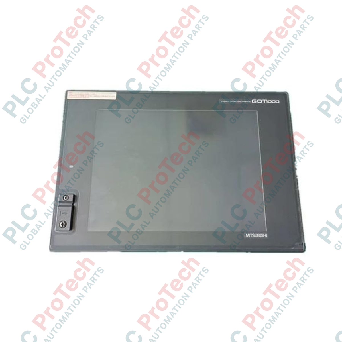
Description
Operating as a high-resolution visualization interface within automated industrial networks, the Mitsubishi Electric GT1575-STBA provides robust operator control capabilities through its high-performance display architecture. Built as part of the established GOT1000 platform, this 10.4-inch SVGA human-machine interface displays technical parameters and machine graphics with high clarity using a 65,536-color TFT liquid crystal panel. The unit features built-in flash memory for safe operating system and project data preservation, paired with wide input-voltage tolerance suitable for global electrical standards.
Features
-
High-Resolution Display: 800 x 600 pixel SVGA matrix optimized for detailed plant mimic diagrams.
-
Flexible Color depth: Selectable 256 or 65,536 color rendering to optimize memory utilization and graphic presentation.
-
Adjustable Backlight: 8-level software and manual contrast/luminance tuning up to 350 cd/m2.
-
Robust Solid-State Storage: 9 Megabytes of internal C-drive flash memory ensures project files remain intact during sustained power failures.
-
Universal AC Power Input: Built-in power supply accommodating 100 to 240 V AC direct connection.
Applications
- Automotive manufacturing and robot-cell monitoring stations.
- Water treatment plant municipal telemetry and control.
- Food processing and high-speed packaging equipment.
- Boiler and steam generator thermal monitoring systems.
Technical Specifications
| Parameter |
Specification Value |
| Manufacturer |
Mitsubishi Electric |
| Model Code |
GT1575-STBA |
| Display Technology |
TFT Color LCD |
| Screen Size (Diagonal) |
10.4 inches (264 mm) |
| Resolution |
800 x 600 dots (SVGA) |
| Active Display Area |
211 mm (W) x 158 mm (H) |
| Input Voltage |
100 to 240 V AC (+10%, -15%) |
| Supply Frequency |
50 / 60 Hz (+/- 5%) |
| Power Consumption |
26 Watts or less (Max 90VA apparent power) |
| Internal Project Memory |
9 Megabytes flash memory (C-drive) |
| Ambient Operating Temp |
0 to 50 degC |
| Physical Dimensions |
303 mm (W) x 214 mm (H) x 49 mm (D) |
| Weight |
2.3 kg (5.07 lbs) |
| Shipping Weight (Calculated) |
4.0 kg (8.82 lbs) |
| Country of Origin |
Japan |
Connections and Interfaces
| Port / Slot Channel |
Connection Function Assignment |
| RS-232 Port |
D-sub 9-pin (male) for point-to-point PLC communication or PC project transfer |
| RS-422/485 Port |
D-sub 9-pin (female) for multi-drop serial PLC connections |
| USB Interface |
USB Mini-B port for high-speed OS and programming interface updates |
| CF Card Interface |
Type I CompactFlash slot for data logging, recipe handling, and system backups |
| Extension Unit Slots |
Accepts fieldbus adapters (e.g., CC-Link, MELSECNET/10, or Ethernet communication modules) |
Empirical Engineering Insights
Alternative Models & Compatibility
The GT1575-STBA belongs to the legacy GOT1000 family. When planning system upgrades, the GT2710-STBA from the GOT2000 series serves as the primary physical alternative. Project configuration files (.g2w format) can be scaled and converted within GT Works3 software. Be aware that communication option cards used on the rear of the GT15 platform are not compatible with GT27 slots, requiring direct Ethernet or equivalent upgrade modules.
Application Pitfalls & Engineering Notes
Backlight longevity is rated at 50,000 operational hours under a nominal 25 degC ambient climate. Operating inside poorly ventilated enclosures where internal temperatures exceed 40 degC will cause accelerated luminance decay and shift the color spectrum. For continuous processes, implement the automatic backlight shutoff utility triggered by a screen-saver timer to extend active component lifespans.
Commissioning & Wiring Tips
Industrial high-frequency noise can cause capacitive grid interference, leading to inaccurate touch coordinate detection. To mitigate this risk, isolate the Frame Ground (FG) terminal of the display power connector and ground it using a dedicated class-D ground point (resistance below 100 ohms). Keep power routing separate from motor-drive cables and high-voltage circuit runs.
Installation Guidelines
CRITICAL WARNING: Isolate all incoming electrical energy circuits from the target control enclosure prior to commencing mechanical installation. Allow up to 5 minutes for integrated bus-capacitance voltages to safely bleed down to non-hazardous levels. Do not attempt live maintenance.
1
Ensure the cutout dimensions in the cabinet door measure exactly 289 mm (W) by 200 mm (H). Deburr all cut metal surfaces to avoid damaging the environmental seal.
2
Examine the pre-installed moisture-proof packing gasket on the rear rim of the HMI bezel. Verify there are no tears, debris, or misalignments that could compromise IP67F ingress protection.
3
Insert the unit into the cutout and hand-tighten the mounting brackets progressively in a cross-pattern to a target torque range of 0.36 to 0.48 N-m to maintain an even, dust-tight seal.