Description
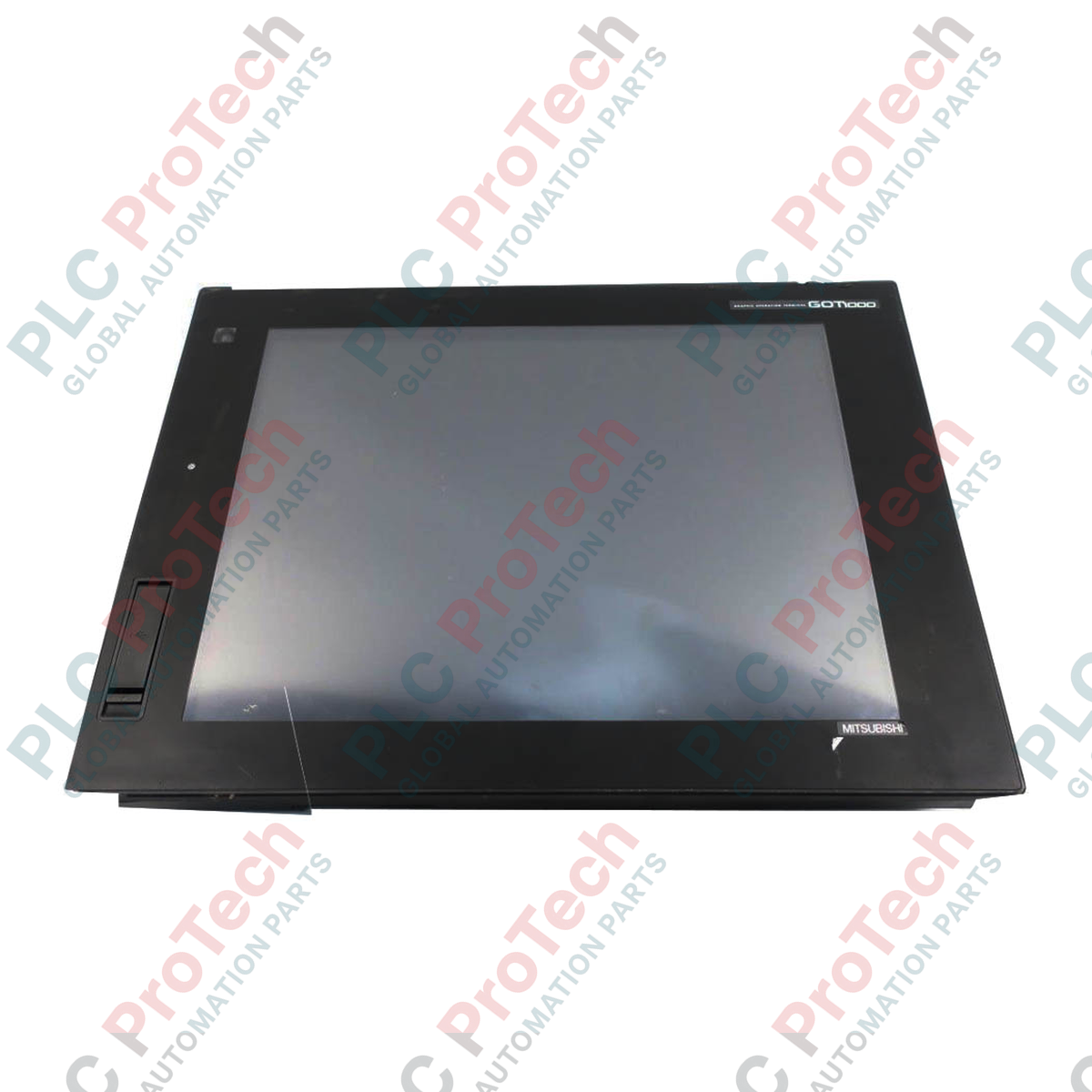
Engineered to deliver high-resolution monitoring and robust machine control, the Mitsubishi Electric GT1695M-XTBA-C stands as an elite 15-inch human-machine interface (HMI) within the legacy GOT1000 platform. This unit provides process-critical visualization in demanding industrial environments, combining a vivid TFT color display with expansive memory capacity and multiple communication interfaces. Designed to withstand mechanical stress and harsh atmospheric conditions, it serves as a reliable central control node for plant-floor diagnostics, parameter adjustment, and complex process automation workflows.
Key Features
-
High-Resolution Display: 15-inch TFT color screen supporting crisp XGA resolution (1024 x 768 pixels) for detailed process screens.
-
Multilingual Support: Dynamic language switching capabilities for global deployments.
-
Expansive Connectivity: Integrated Ethernet, RS-232, and RS-422/485 serial communication interfaces.
-
Storage Expansion: Dedicated CompactFlash (CF) card slot for historical data logging, recipe storage, and OS backups.
-
Environmental Resilience: Heavy-duty construction conforming to international shock, vibration, and atmospheric standards.
Applications
- Automotive assembly line monitoring and robotic cell integration.
- Complex packaging and converting machinery control panels.
- Water and wastewater municipal treatment monitoring.
- Semiconductor manufacturing cleanroom diagnostic interfaces.
Technical Specifications
| Parameter |
Value |
| Manufacturer |
Mitsubishi Electric |
| Model Number |
GT1695M-XTBA-C |
| Product Series |
GOT1000 Series |
| Display Size |
15 Inches |
| Display Type |
TFT Color LCD |
| Resolution |
XGA (1024 x 768 Pixels) |
| Power Supply |
100 V AC to 240 V AC (+10%, -15%) |
| Operating Ambient Temperature |
0 to 50 degC |
| Storage Ambient Temperature |
-20 to 60 degC |
| Operating Ambient Humidity |
10% to 90% RH, Non-Condensing |
| Impact Resistance |
Conforming to JIS B 3502 and IEC 61131-2 (147 m/s2) |
| Ingress Protection (Front) |
IP67F (When installed using appropriate gasket) |
| Weight |
5.0 kg |
| Shipping Weight (Calculated) |
8.0 kg |
Connections and Interfaces
| Interface / Port |
Connector Type |
Functional Purpose |
| Ethernet |
RJ45 |
Host controller communication & programming uploading/downloading |
| RS-232 |
D-Sub 9-pin Male |
Direct connection to legacy PLCs, barcode readers, or printers |
| RS-422/485 |
D-Sub 9-pin Female |
Multi-drop serial networks with compatible controllers |
| USB Host |
Type A |
External keyboard/mouse input and USB memory stick data storage |
| USB Device |
Mini-B |
Direct PC transfer point for GT Works3 screen design software |
Alternative Models & Compatibility
The GT1695M-XTBA-C acts as a direct physical and functional successor to the GT1595-XTBA model. While screen project data can be migrated seamlessly using Mitsubishi's GT Works3 software, engineers must verify that communications protocol drivers are updated to correspond with newer firmware configurations. Mounting bracket footprints remain compatible, easing physical cabinet swap-outs.
Application Pitfalls & Engineering Notes
To prevent thermal accumulation when mounting the terminal in completely sealed IP67 enclosures, ensure a minimum of 100mm of vertical clearance is maintained from any heat-generating auxiliary components (such as variable frequency drives or large power supplies). Operating this unit constantly at its upper thermal limit of 50 degC will reduce the service life of the CCFL backlight assembly.
Commissioning & Wiring Tips
Ensure that the functional ground (FG) terminal on the main power supply block is connected directly to a dedicated class-D ground point (resistance of 100 ohms or less) using a minimum 2 mm2 ground wire. Failure to isolate the terminal ground from high-current machinery ground paths may result in intermittent touch screen offset issues or communications drops on serial channels.
Installation Guidelines
CRITICAL WARNING
Isolate all electrical supply circuits feeding the enclosure before beginning mechanical or electrical installation of this terminal. High voltage (up to 240V AC) is present on the power connection terminals. Allow internal storage capacitors to discharge completely for at least 10 minutes prior to handling internal communication expansion modules or wiring paths.
1
Verify panel cutout dimensions correspond precisely to the GT1695 standard installation template to maintain the IP67F dust and liquid seal.
2
Insert the terminal into the cutout from the front, ensuring the rubber sealing gasket is flat and free of twists.
3
Secure the provided mounting brackets to the terminal body rear channels, tightening the mounting screws evenly to the recommended torque specifications (0.36 to 0.48 N-m) to prevent panel distortion.
4
Connect the isolated AC power wiring and ensure standard communication cable shields are grounded at the controller side.