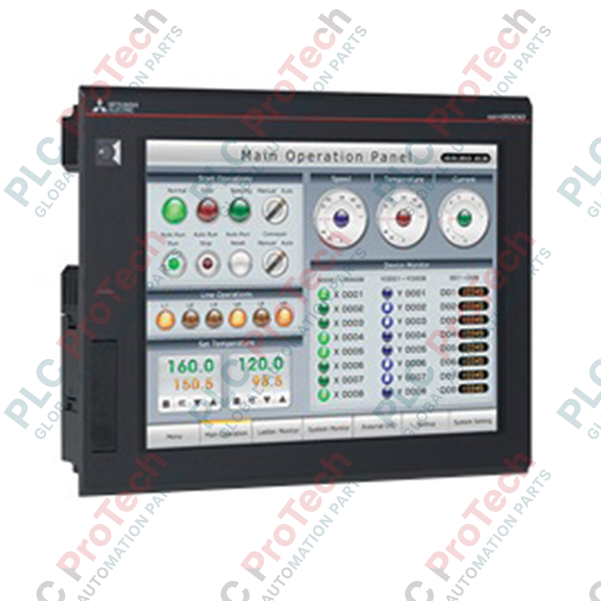
Entwickelt für leistungsstarke industrielle Visualisierung, dient das Mitsubishi Electric GT2708-STBA als fortschrittliches Mensch-Maschine-Interface innerhalb der GOT2000-Serie, das Multi-Touch-Gestensteuerung und ein 8,4-Zoll SVGA TFT-Display integriert. Dieses Gerät bietet Bedienern eine intuitive, smartphoneähnliche Steuerung komplexer Industrieprozesse und gewährleistet hohe Auflösung sowie robuste physische Haltbarkeit in anspruchsvollen Schaltschrankumgebungen.
Hauptmerkmale
-
Hochauflösendes Display: 8,4-Zoll SVGA TFT-Farbdisplay mit 800 x 600 Auflösung für präzise grafische Darstellung.
-
Multi-Touch-Funktionalität: Unterstützt Gestensteuerungen wie Kneifen, Zoomen und Wischen für verbesserte Benutzerinteraktion.
-
Flexible Stromversorgung: Kompatibel mit einem weiten Bereich an Wechselspannungen (100 bis 240 VAC) für weltweite elektrische Standards.
-
Umweltresistenz: Entspricht IEC 61131-2 Standards für hohe Vibrations- und Stoßfestigkeit.
-
Effizientes Wärmemanagement: Selbstkühlendes Design, optimiert für platzsparende Montage im Schaltschrank.
Anwendungen
- Visualisierung in der Automobilmontage und Roboterzellen
- Überwachungssysteme für Wasser- und Abwasserbehandlung
- Verpackungs-, Materialhandhabungs- und Fördermaschinen
- Steuerstationen für Lebensmittel- und Getränkeverarbeitung
Technische Spezifikationen
| Parameter |
Spezifikation |
| Hersteller |
Mitsubishi Electric |
| Modellnummer |
GT2708-STBA |
| Displaytyp |
TFT Farb-LCD |
| Bildschirmgröße |
8,4 Zoll |
| Auflösung |
SVGA (800 x 600 Pixel) |
| Rahmenfarbe |
Schwarz |
| Eingangsspannung |
100 bis 240 VAC (+10 %, -15 %) |
| Stromverbrauch |
41 W oder weniger (maximale Last), 15 W (Einzelgerät) |
| Einschaltstrom |
60 A oder weniger (2 ms, Umgebungstemperatur 25 °C) |
| Betriebstemperatur |
0 bis 55 °C (horizontale Montage), 0 bis 50 °C (vertikale Montage) |
| Lagertemperatur |
-20 bis 60 °C |
| Umgebungsfeuchtigkeit |
10 bis 90 % relative Luftfeuchtigkeit (nicht kondensierend) |
| Stoßfestigkeit |
Entspricht JIS B 3502, IEC 61131-2 (147 m/s², 15G) |
| Durchschlagfestigkeit |
1500 VAC für 1 Minute zwischen Stromanschluss und Erde |
| Isolationswiderstand |
10 MOhm oder höher (500 VDC) |
| Außenmaße |
24,1 cm x 19,4 cm x 5,2 cm |
| Nettogewicht |
1,5 kg (ohne Montagehalterungen) |
| Versandgewicht (berechnet) |
1,8 kg |
| Verpackungsmaße (berechnet) |
30,0 cm x 25,0 cm x 12,0 cm |
Anschlusssockel-Spezifikationen
| Anschlussparameter |
Anforderung |
| Anwendbare Drahtgröße |
0,75 bis 2 mm² |
| Kompatible Klemmklemmen |
M3-Schraubklemmen (RAV1.25-3, V2-S3.3, V2-N3A, FV2-N3A) |
| Anzugsdrehmoment |
0,5 bis 0,8 N·m |
Alternative Modelle & Kompatibilität
Das GT2708-STBA ist ein direkter moderner Ersatz für ältere GT1675- und GT1575-Serien-HMIs. Während die Ausschnittmaße im Schaltschrank weitgehend kompatibel sind, müssen Unterschiede in Bildschirmauflösung und Seitenverhältnis bei der Projektmigration in GT Works3 überprüft werden. Stellen Sie sicher, dass die GT Works3-Software auf die neueste Version aktualisiert ist, um alle Multi-Touch-Gestenkonfigurationen, die für die GT27-Hardware typisch sind, zu unterstützen.
Anwendungsfallen & technische Hinweise
Beachten Sie, dass die maximale Betriebstemperatur abhängig von der Ausrichtung ist. Bei horizontaler Montage arbeitet das Gerät sicher bis zu 55 °C; bei vertikaler Installation ist die maximale Betriebstemperatur auf 50 °C begrenzt. Stellen Sie einen Mindestabstand von 100 mm zu anderen Schaltschrankkomponenten sicher, um eine ordnungsgemäße natürliche Konvektion zu ermöglichen, da dieses HMI vollständig auf Selbstkühlung angewiesen ist.
Inbetriebnahme- & Verdrahtungstipps
Um elektrische Störgeräusche zu vermeiden, muss der Erdungsanschluss an eine dedizierte Klasse-D-Erde (Erdungswiderstand von 100 Ohm oder weniger) mit einem Mindestquerschnitt von 2 mm² angeschlossen werden. Vermeiden Sie es, Stromversorgungsleitungen parallel zu Hochspannungs- oder Hochstrom-Motorantriebskabeln zu verlegen. Ziehen Sie die M3-Klemmschrauben strikt im Bereich von 0,5 bis 0,8 N·m an, um Schäden an den Klemmen oder lockere Verbindungen durch Vibrationen zu verhindern.
Installationsrichtlinien
KRITISCHE WARNUNG
Isolieren und sperren Sie alle AC-Stromquellen, bevor Sie versuchen, die HMI-Einheit zu installieren, zu verdrahten oder zu entfernen. Ein unvollständiges Abschalten des Systems kann zu schweren Stromschlägen, Geräteschäden oder unerwartetem Systemverhalten führen.
1
Bereiten Sie den Schaltschrankausschnitt gemäß den angegebenen Maßen vor (für die Standardmontage wird ein Ausschnitt von 227 mm x 176 mm empfohlen).
2
Stellen Sie sicher, dass die wasserdichte Dichtung ordnungsgemäß in der HMI-Nut sitzt, um die Umweltdichtheit zu gewährleisten.
3
Setzen Sie das HMI in den Schaltschrankausschnitt ein und sichern Sie es mit den mitgelieferten Montagewinkeln, indem Sie die Schrauben mit dem angegebenen Drehmoment anziehen, um eine Verformung des Schaltschranks zu verhindern.
4
Schließen Sie die AC-Stromversorgungsleitungen mit M3-Klemmklemmen an den Klemmenblock an und achten Sie dabei auf die korrekte Polarität und eine solide Erdung.