Description
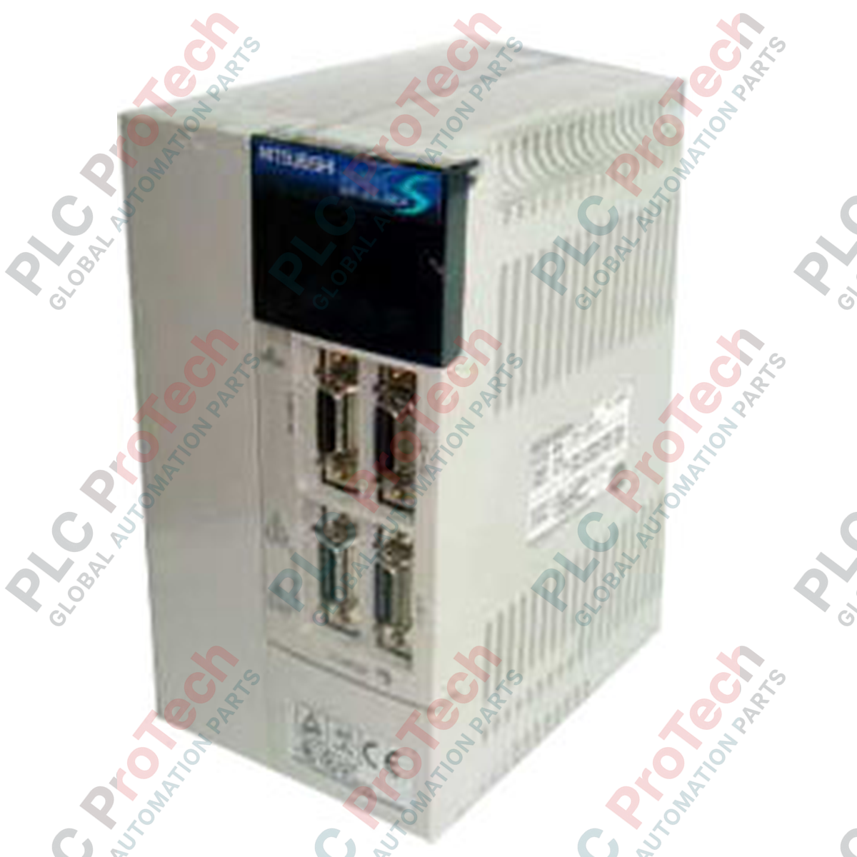
Executing high-precision position and velocity profiles, the Mitsubishi Electric MR-J2S-350B is a 3.5 kW digital servo amplifier designed for seamless integration within the MELSERVO J2-Super control architecture. This module operates on a high-speed SSCNET (Servo System Controller Network) synchronous serial bus, facilitating real-time motion synchronization and eliminating complex analog command wiring. Engineered with a sinusoidal PWM control and current control system, it provides optimal torque response and minimal thermal output. The drive incorporates a built-in dynamic brake for emergency stopping cycles, while its advanced internal protection networks continuously monitor operational parameters to shield both the amplifier and the connected low-inertia or medium-inertia rotary servomotor from electrical or thermal overload conditions.
Key Features
-
SSCNET Bus Integration: Uses fiber-optic or high-speed serial communications to drastically reduce cabling and mitigate electromagnetic noise interferences.
-
High Response Rate: Delivers a speed frequency response of 550 Hz or greater, satisfying high-speed positioning requirements.
-
Comprehensive Safety Shutdowns: Integrates overcurrent, regenerative overvoltage, overload, and absolute encoder fault diagnostics directly into the control loop.
-
Sinusoidal PWM Control: Optimizes current delivery to reduce motor torque ripple and thermal losses during continuous duty cycles.
-
Forced-Air Cooling: Integrated cooling fan maintains optimal power stage temperatures under demanding ambient conditions.
Applications
- High-speed multi-axis packaging machinery requiring microsecond synchronization.
- Automated pick-and-place assembly lines utilizing high-resolution absolute feedback.
- Metalworking CNC feed axes requiring robust positioning torque.
- Precision semiconductor handling equipment operating in cleanroom panel spaces.
Technical Specifications
| Parameter |
Specification Values |
| Manufacturer |
Mitsubishi Electric |
| Model Series |
MELSERVO J2-Super (MR-J2S Series) |
| Rated Power Output |
3.5 kW |
| Primary Input Voltage |
3-phase 200 to 230 VAC, 50/60 Hz |
| Permissible Voltage Fluctuation |
3-phase 170 to 253 VAC |
| Permissible Frequency Fluctuation |
+/- 5% |
| Control Method |
Sinusoidal PWM Control / Current Control System |
| Dynamic Brake |
Built-in |
| Enclosure Rating |
IP00 (Open structure, fan-cooled) |
| Operating Temperature Range |
0 to 55 degC (no freezing) |
| Storage Temperature Range |
-20 to 65 degC (no freezing) |
| Ambient Humidity Limit |
90% RH maximum (non-condensing) |
| Maximum Elevation |
1000m or less above sea level |
| Maximum Oscillation Tolerance |
5.9 m/s² maximum |
| Shipping Weight (Calculated) |
3.0 kg |
Connections and Interfaces
| Connector / Terminal |
Function / Assignment |
| L1 / L2 / L3 |
Main 3-phase AC power input terminal block |
| L11 / L21 |
Control circuit power supply input (single-phase) |
| U / V / W |
Three-phase motor output to servomotor winding |
| CN1A |
SSCNET bus connection input port (from system controller or previous axis) |
| CN1B |
SSCNET bus connection output port (to downstream axis or terminal connector) |
| CN2 |
Feedback encoder connection port (for linear/rotary absolute or incremental signals) |
| CN3 |
RS-232C / RS-422 serial interface port (for parameter tuning via MR Configurator) |
| P / C / D |
External regenerative brake resistor interface terminals |
Empirical Engineering Insights
Alternative Models & Compatibility
The MR-J2S-350B relies specifically on the legacy SSCNET protocol. It cannot be directly swapped with newer MR-J4-350B or MR-J5-350B units without incorporating the MR-J4-T20 SSCNET compatibility interface or converting the system network topology to SSCNET III/H. To retain existing fiber routing without controller modifications, ensure direct MR-J2S replacement. When substituting from analog-command models (e.g., MR-J2S-350A), please note that the control board, control cables, and PLC output modules must be completely reconfigured to accommodate the network-style command structure.
Application Pitfalls & Engineering Notes
Because this amplifier has an IP00 open-frame physical construction, it must be mounted inside a sealed, forced-ventilation or air-conditioned electrical control cabinet. Infiltration of conductive metallic dust, oil mists, or humidity will cause immediate catastrophic failure of the main high-voltage DC bus capacitors. If operating under high-frequency start-stop cycles, monitor the thermal capacity of the internal regenerative resistor; if fault code AL.30 (Regenerative Error) is persistently triggered, an external cooling fan must be directed at the heat sinks, or a high-capacity external regenerative option must be wired between terminals P and C with the factory-installed jumper wire removed.
Commissioning & Wiring Tips
When routing SSCNET optical fiber cables to the CN1A and CN1B ports, do not violate the minimum physical bend radius of 25mm. Tight kinks or sharp bends will degrade optical transmission, resulting in intermittent AL.16 (Encoder Communications Error) or network dropout states. For absolute position configurations, remember to connect a fresh MR-BAT lithium battery unit to the designated port. Replacing the battery must be performed with the control circuit power supply (L11/L21) energized; failing to power the drive control board during battery swaps will result in immediate erasure of the reference origin position, requiring a full re-homing calibration sequence.
Installation Guidelines
CRITICAL WARNING: HIGH VOLTAGE RISK
Isolate all primary three-phase AC power lines before initiating mechanical or electrical installation. After de-energizing, wait a minimum of 15 minutes to allow internal high-voltage DC bus capacitors to discharge to safe threshold levels. Measure terminal voltage across the P and N terminal points with a calibrated digital multimeter before contacting wiring or screw terminals.
1
Mount the servo amplifier vertically on a flat, unpainted metal panel to maximize thermal dissipation and ground surface contact. Leave a minimum space of 40mm at the top/bottom and 10mm on both sides for sufficient airflow.
2
Connect the protective earth (PE) ground terminal directly to the panel backplane with a heavy-gauge, low-impedance conductor. Do not daisy-chain ground lines with other high-power drives or industrial power sources.
3
Wire the control input power terminals (L11, L21) separate from the main drive power feed (L1, L2, L3) via an independent circuit breaker, maintaining diagnostic feedback capabilities during main power-down safety shutdowns.
4
Plug in the motor encoder cable to the CN2 port, securing the retention screws fully to prevent intermittent encoder feedback loss due to machinery vibration.