Description
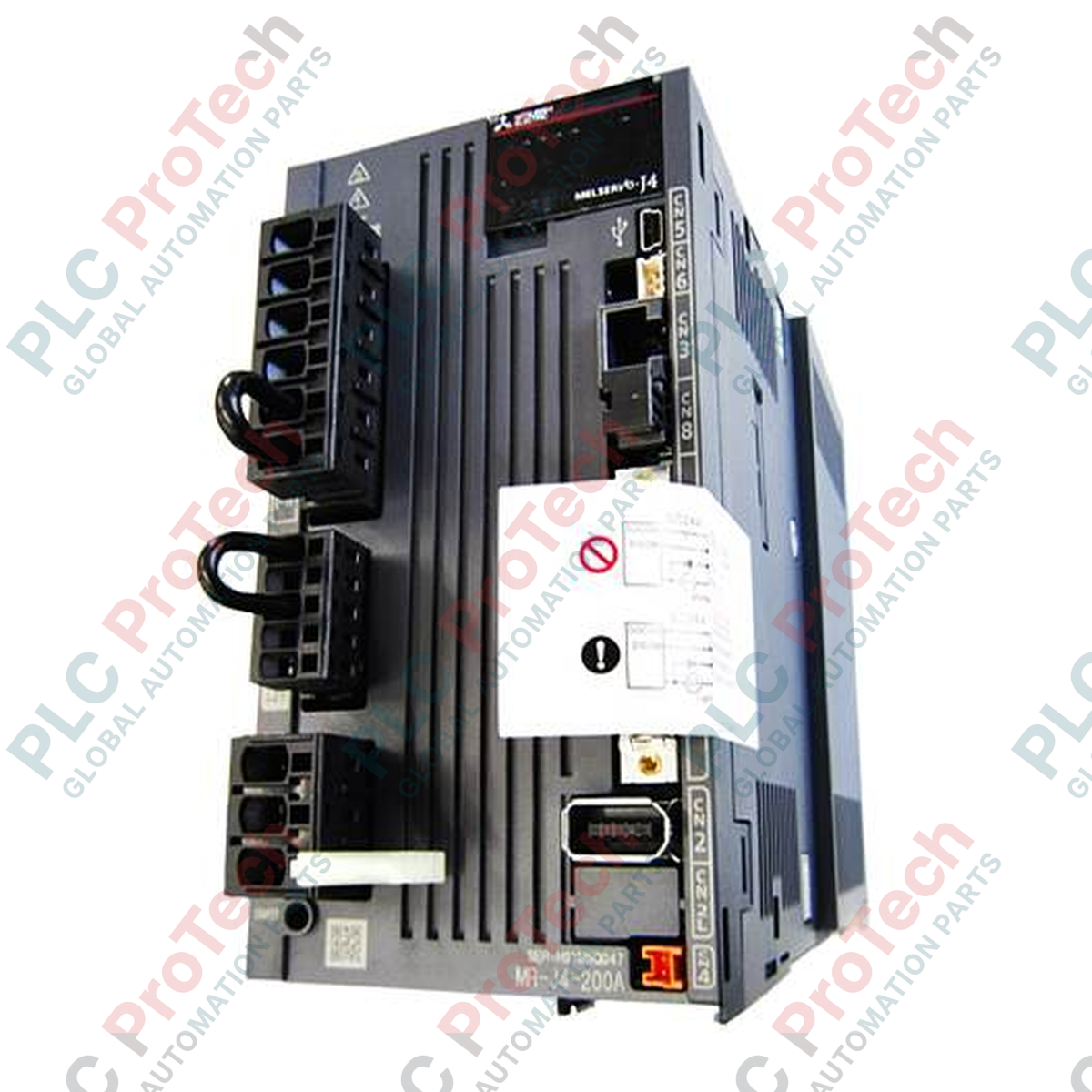
Integrating seamlessly into high-precision motion topologies, the Mitsubishi Electric MR-J4-200A delivers highly responsive closed-loop control as a general-purpose, single-axis servo drive. This unit is specifically engineered to operate within the 200V class, offering a robust 2.0 kW rated output compatible with low and medium-inertia rotary servo motors. Built with advanced digital signal processors, the servo amplifier utilizes general-purpose interfaces, accepting pulse train commands up to 4 Mpulses/s and analog voltage inputs for speed or torque regulation. By eliminating complex network configurations, this model provides direct integration with legacy PLCs and standard positioning modules while maintaining the dynamic performance of the MELSERVO-J4 platform.
Features
-
General-Purpose Interface: Flexible command options supporting pulse-train input (differential line driver or open collector) and +/-10V analog voltage control.
-
Real-Time Auto Tuning: One-touch tuning algorithm automatically measures mechanical resonance frequencies and configures optimal servo gains.
-
Advanced Vibration Suppression: Incorporates Mitsubishi Electric Vibration Suppression Control II to minimize transient oscillations on the machine end.
-
High-Resolution Feedback compatibility: Capable of processing absolute encoder inputs to secure micron-level positioning repeatability.
-
Integrated Safety Function: Features native Safe Torque Off (STO) input channels to simplify machine safety system compliance.
Applications
- High-speed pick-and-place packaging systems.
- Multi-axis gantry positioning and Cartesian coordinate robots.
- Semiconductor fabrication handling systems and wafer positioning.
- Automated rotary indexing tables and metalforming machinery.
Technical Specifications
| Parameter |
Specification |
| Manufacturer |
Mitsubishi Electric |
| Model Number |
MR-J4-200A |
| Series Name |
MELSERVO-J4 |
| Rated Output Power |
2.0 kW |
| Main Circuit Power Supply |
3-phase 200 to 240 V AC, 50/60 Hz |
| Control Circuit Power Supply |
1-phase 200 to 240 V AC, 50/60 Hz |
| Rated Output Current |
11.0 A |
| Control Interface Type |
Pulse train / Analog voltage input |
| Cooling Method |
Force-cooled (built-in cooling fan) |
| IP Rating |
IP20 (excluding terminal blocks/connectors) |
| Shipping Weight (Calculated) |
3.5 kg |
Connections and Interfaces
| Connector / Terminal |
Functional Assignment |
| L1 / L2 / L3 |
Main circuit 3-phase AC power input |
| L11 / L21 |
Control circuit single-phase AC power input |
| U / V / W |
Servo motor power outputs (3-phase) |
| CN1 |
I/O signal connector (Pulse input, analog commands, and digital outputs) |
| CN2 |
High-resolution motor encoder feedback interface |
| CN3 |
RS-422/USB communication port for PC utility (MR Configurator2) |
| CN8 |
Safe Torque Off (STO) terminal connector |
Empirical Engineering Insights
Alternative Models & Compatibility
The MR-J4-200A features the "A" general-purpose analog/pulse interface and is physically and electronically incompatible with the "B" suffix units (such as MR-J4-200B), which use SSCNET III/H fiber-optic network communication. When replacing a legacy MR-J3-200A unit, parameter conversion must be performed using MR Configurator2, and motor matching should be verified since MR-J4 series drives are paired with HG series servo motors.
Application Pitfalls & Engineering Notes
During dynamic decelerations or high-inertia vertical axis operations, the internal regenerative capacity of this 2.0 kW drive can become saturated, triggering an AL.30 (Regenerative error). If this occurs, do not increase the fault threshold; instead, remove the shorting bar between the P+ and D terminals and wire an external regenerative resistor. Always ensure the cabinet has at least 10 mm of clear spacing on either side of the unit to allow the integrated fan to dissipate thermal exhaust efficiently.
Commissioning & Wiring Tips
To avoid encoder transmission faults (AL.16), the CN2 encoder shield must be clamped directly to the amplifier’s grounded installation plate using a metallic grounding clip. If long pulse-train lines are required, avoid open-collector wiring and always implement differential line-driver control signals at CN1 to optimize noise immunity and maintain positioning consistency at high frequency commands.
Installation Guidelines
CRITICAL WARNING: Electrical Shock and Arc Flash Hazard
Isolate and verify de-energized status of all input power sources (L1, L2, L3 and L11, L21) before initiating any physical terminal modifications. Allow at least 15 minutes post-power-down for the internal bus capacitors to bleed residual charge below a safe threshold (50V DC) prior to removing any terminal protective covers.
1
Mount the amplifier vertically on a flat, non-flammable backplate within an IP54 or better sealed industrial enclosure to protect the internal cooling fan from fine dust and debris.
2
Wire control power to L11 and L21 first, followed by main power to L1, L2, and L3. Connect the earth terminal directly to the enclosure's main ground bar using a low-impedance copper conductor.
3
Connect the encoder cable to CN2 and control I/O to CN1. Ensure all connector thumb-screws are firmly seated to prevent signal interruption during operational vibration.