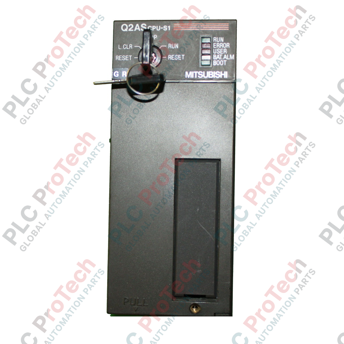
Die Verwaltung komplexer Automatisierungsabläufe in platzbeschränkten Schaltschränken ist die Hauptaufgabe der Mitsubishi Electric Q2ASCPU-S1, eines leistungsstarken kompakten CPU-Moduls für die Steuerungsplattform MELSEC QnAS Series. Entwickelt für schnelle Befehlsausführung und umfangreiche Speicherkapazität, bewältigt dieser Prozessor anspruchsvolle Industrieanwendungen mit kurzen Zykluszeiten und großem Rezeptspeicher bei kompakter Bauweise.
Hauptmerkmale
-
60k Schritte Programmkapazität: Unterstützt groß angelegte Steuerungslogik, komplexe Algorithmen und umfangreiche Rezeptverwaltung.
-
Hochgeschwindigkeitsverarbeitung: Erreicht eine Befehlsausführungsgeschwindigkeit von 0,15 Mikrosekunden für schnelle Systemreaktionen.
-
Erweiterte E/A-Steuerung: Direkte Adressierung und Verwaltung von bis zu 1024 lokalen und entfernten E/A-Punkten.
-
Integrierte Kommunikation: Eingebaute RS-232C-Schnittstelle ermöglicht direkte Verbindung zu HMIs, Programmier-PCs und Peripheriegeräten.
-
Rückwärtskompatibilität: Nahtlose Integration mit bestehenden MELSEC AnS Serien Backplanes und spezialisierten E/A-Modulen.
Anwendungen
- Mehrachsige Verpackungs- und Etikettiermaschinen mit Hochgeschwindigkeits-Synchronisation.
- Automatisierte Materialhandhabung, Sortierung und Förderverteilernetze.
- Verteilte Steuerungssysteme für Wasser- und Abwasseranlagen.
- Lebensmittel- und Getränke-Batch-Verarbeitungslinien mit komplexen Rezeptkonfigurationen.
Technische Spezifikationen
| Parameter |
Spezifikation |
| Hersteller |
Mitsubishi Electric |
| Modell / Artikelnummer |
Q2ASCPU-S1 (Q2AS-CPU-S1) |
| Steuerungsmethode |
Gespeichertes Programm mit Wiederholbetrieb |
| Programmkapazität |
60k Schritte |
| E/A-Punkte |
1024 Punkte |
| Grundlegende Befehlsausführungsgeschwindigkeit |
0,15 Mikrosekunden (LD-Befehl) |
| Interner Stromverbrauch (5 VDC) |
300 mA (0,3 A) |
| Kommunikationsschnittstellen |
RS-232C (9-poliger D-Sub), Programmierschnittstelle |
| Unterstützte Speichertypen |
RAM, ROM, EEPROM (über optionale Speicherkassette) |
| Betriebstemperatur |
0 bis 55 °C |
| Lagertemperatur |
-20 bis 75 °C |
| Herkunftsland |
Japan |
| Versandgewicht (berechnet) |
0,45 kg |
| Verpackungsmaße (berechnet) |
150 x 110 x 45 mm |
Anschlüsse und Schnittstellen
| RS-232C Pin |
Signalname |
Beschreibung |
| Pin 1 |
CD |
Träger erkannt |
| Pin 2 |
RXD |
Daten empfangen |
| Pin 3 |
TXD |
Daten senden |
| Pin 4 |
DTR |
Datenendgerät bereit |
| Pin 5 |
SG |
Signalmasse |
| Pin 6 |
DSR |
Datenbereit |
| Pin 7 |
RTS |
Request to Send |
| Pin 8 |
CTS |
Clear to Send |
Empirische technische Erkenntnisse
Alternative Modelle & Kompatibilität
Die Q2ASCPU-S1 ist ein direkter, leistungsstarker Ersatz für die Standard-Q2ASCPU (beschränkt auf 28k Schritte). Sie hat identische Abmessungen und Backplane-Montagekonfigurationen. Beim Umstieg von älteren AnS-Serien-CPUs (z. B. A1SCPU oder A2SCPU) ermöglicht die Q2ASCPU-S1 die Beibehaltung des vorhandenen I/O-Chassis und der Module, erfordert jedoch eine Programmkonvertierung über GX Developer oder GX Works2, um den aktualisierten Befehlssatz und die Registerstrukturen abzubilden.
Anwendungsfallen & technische Hinweise
Diese CPU verwendet flüchtigen RAM für die primäre Programmausführung. Um Programmverluste bei längeren Stromausfällen zu vermeiden, muss eine funktionierende Backup-Batterie (A6BAT) vorhanden sein. Leuchtet die „BAT.ERR“-LED an der Frontplatte, muss die Batterie innerhalb von 7 Tagen ersetzt werden. Für kritische Anwendungen wird dringend empfohlen, eine optionale nichtflüchtige Speicherkassette (z. B. Q2MEM-8MBA) zu installieren, um eine permanente Sicherung der Parameter und Logik zu gewährleisten.
Inbetriebnahme- & Verdrahtungstipps
Beim Aufbau der seriellen Kommunikation über den integrierten RS-232C-Anschluss stellen Sie sicher, dass Ihre Kabelkonfiguration den Handshake-Anforderungen Ihres angeschlossenen Geräts entspricht. Bei Verwendung einer Standard-3-Draht-Verbindung (TXD, RXD, SG) müssen Sie die Pins 7 (RTS) und 8 (CTS) auf der CPU-Seite überbrücken, um Kommunikationszeitüberschreitungen zu vermeiden. Wählen Sie bei der Konfiguration von GX Developer als PLC-Typ „Q2AS(H)“, um die vollständige Befehls-Kompatibilität beim Download zu gewährleisten.
Installationsrichtlinien
KRITISCHE WARNUNG
Gefahr von elektrischem Schlag und Geräteschäden. Schalten Sie die Hauptstromversorgung der Basiseinheit und aller zugehörigen externen E/A-Schaltungen vollständig ab, bevor Sie das CPU-Modul montieren oder entfernen. Andernfalls kann es zu Schäden am Backplane-Bus oder zu Fehlfunktionen der CPU kommen.
1
Richten Sie den Haken am unteren Ende des CPU-Moduls mit dem Modul-Lokalisierungsloch an der Basiseinheit aus.
2
Drücken Sie die Oberseite des Moduls fest gegen die Basiseinheit, bis es sicher in den oberen Verriegelungsmechanismus einrastet.
3
Befestigen Sie das Modul an der Basiseinheit, indem Sie die Modulbefestigungsschraube (M3 x 12) mit einem Drehmoment von 0,36 bis 0,48 N-m anziehen.
4
Setzen Sie die Speicherkassette ein und schließen Sie den Backup-Batterieanschluss an, bevor Sie die Systemstromversorgung einschalten.