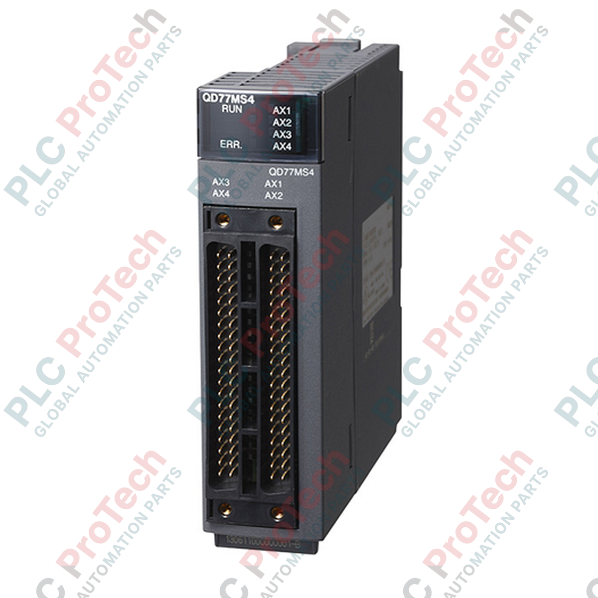
Description
Managing complex positioning profiles and multi-axis synchronization within the MELSEC Q Series architecture is the primary role of the Mitsubishi Electric QD77MS4 Simple Motion Module. This high-density module provides control over up to 4 independent or synchronized axes, utilizing the noise-immune, high-speed SSCNET III/H fiber-optic network. By implementing high-speed operation cycles, it guarantees fast response times and precise coordinate tracking in complex industrial machinery.
Engineers can easily configure advanced motion profiles including Point-to-Point (PTP) positioning, linear and circular interpolation, speed-torque control transitions, and electronic cam profiling directly via GX Works programming software. The physical integration consumes a minimal footprint on the base rack, occupying only 32 standard I/O points.
Key Features
- Multi-axis motion control support for up to 4 axes over a single SSCNET III/H link.
- Ultra-fast execution cycles of 0.88 ms or 1.77 ms for high-speed dynamic tracking.
- Flexible unit configuration enabling independent axis programming in millimeters, inches, degrees, or pulses.
- Advanced transition modes including speed-position and position-speed switching, as well as dedicated speed-torque control.
- High-durability flash memory supporting up to 100,000 write operations for persistent parameter storage.
Applications
- High-speed packaging, cartoning, and continuous horizontal/vertical form-fill-seal machinery.
- Synchronized rotary cutters, flying shears, and precise material winding systems.
- Multi-axis pick-and-place gantry systems and automated component insertion stations.
- Material handling systems requiring strict speed-torque regulation for tension control.
Technical Specifications
| Parameter |
Specification |
| Manufacturer |
Mitsubishi Electric |
| Model Number |
QD77MS4 |
| Series |
MELSEC Q Series |
| Module Type |
Simple Motion Module |
| Number of Control Axes |
4 axes |
| Operation Cycle |
0.88 ms / 1.77 ms |
| Control Modes |
PTP (Point To Point), linear interpolation (up to 4 axes), circular interpolation (2 axes), speed, speed-position, position-speed, speed-torque |
| Control Units |
mm, inch, degree, PLS |
| Occupied I/O Points |
32 points (Intelligent function module assignment) |
| Internal Current Consumption (5 VDC) |
0.6 A |
| Flash ROM Write Capacity |
Max. 100,000 writes |
| Module Weight |
0.16 kg |
| Shipping Weight (Calculated) |
1.50 kg |
Connections and Interfaces
| Port / Connection |
Interface Specification / Function |
| SSCNET III/H Port |
High-speed fiber optic connection (150 Mbps) for direct communication with MR-J4 servo amplifiers. |
| External Input Connection |
Multi-pin front connector for external command signals (such as limit switches, proximity, and stop signals). |
Empirical Engineering Insights
Alternative Models & Compatibility
The QD77MS4 acts as a functional transition path from older QD75 series modules. Note that because it utilizes the SSCNET III/H fiber optic network protocol, it cannot be directly wired via analog or traditional pulse trains to old-generation servo drives. It requires compatible SSCNET III/H compliant servo amplifiers (such as the MELSERVO MR-J4 series) to operate correctly.
Application Pitfalls & Engineering Notes
When routing the fiber-optic cables (SSCNET III/H), ensure the minimum bending radius of the fiber lines does not drop below 25 mm. Exceeding this limit will cause signal attenuation, leading to intermittent communications failures and triggering motion faults (often manifesting as axis dropouts). Additionally, ensure unused ports are covered with dust caps to prevent optical performance degradation.
Commissioning & Wiring Tips
Always match the station numbers assigned via rotary switches on the physical MR-J4 servo amplifiers with the hardware axes configured in the GX Works Simple Motion Module Setting Tool. Misalignment will prevent synchronization during start-up, triggering card initialization errors.
Installation Guidelines
CRITICAL WARNING
Isolate and lock out all external power sources before installing or removing modules from the PLC chassis. Failure to do so can result in electrical shock, physical damage to the backplane connectors, or module failure due to transient voltage surges.
1
Power down the entire system rack and verify zero voltage using an appropriate industrial tester.
2
Align the lower hook of the QD77MS4 module with the mounting slot on the MELSEC Q base unit and press the module firmly onto the backplane connector until it clicks.
3
Secure the module lock-screw to ground the metal chassis to the backplane frame.
4
Connect the SSCNET III/H fiber optic cables until they click firmly into the optical terminal ports.