Description
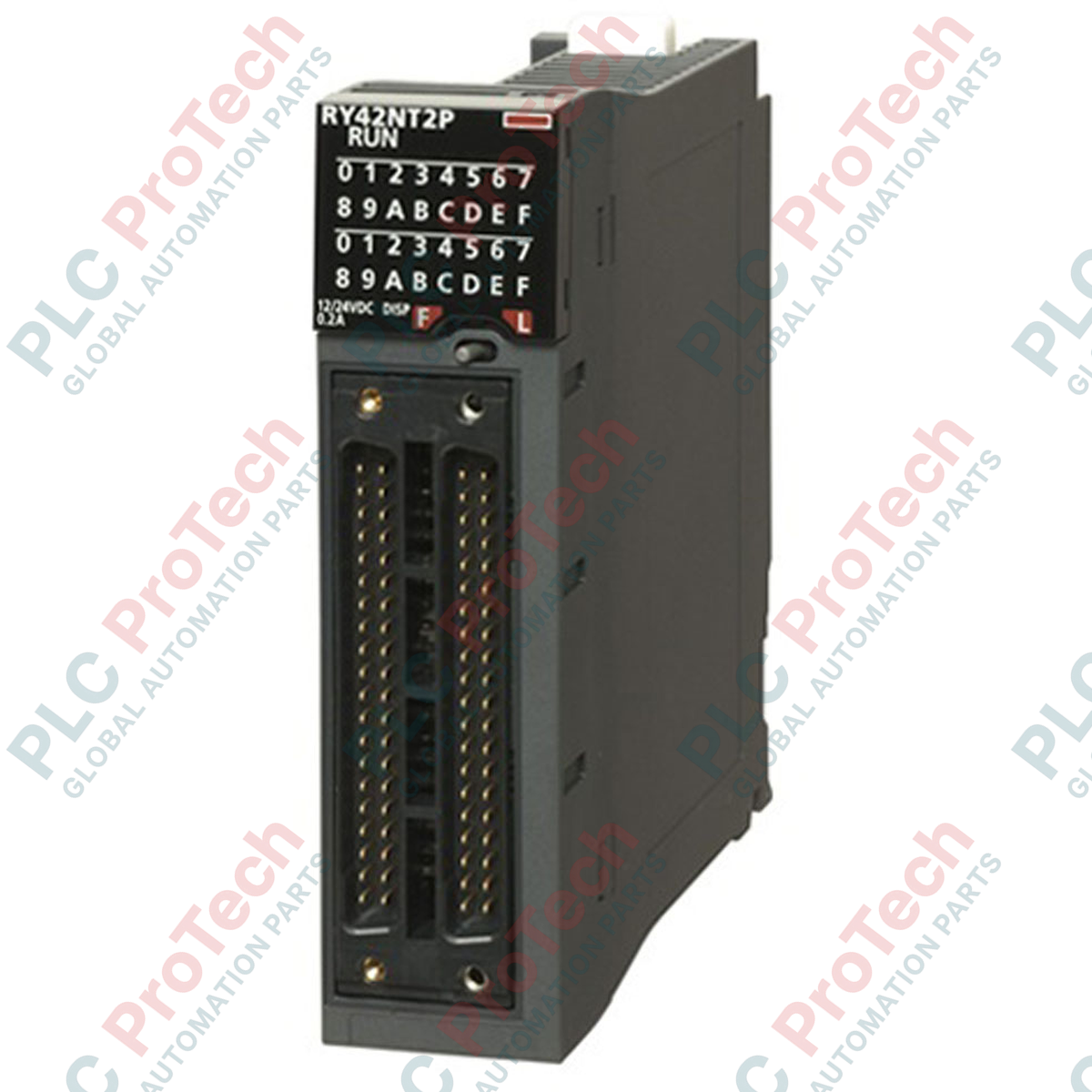
Engineered for high-density industrial control architectures, this 64-point digital output module provides high-speed, reliable transistor switching within the MELSEC iQ-R Series PLC platform. The Mitsubishi Electric RY42NT2P acts as a robust NPN sink-type transistor interface, featuring built-in overcurrent and thermal overload protection to shield critical field circuits and internal hardware from electrical faults. Its ultra-compact dual 40-pin connector layout maximizes I/O density in heavy-duty automation panels while maintaining precise response times.
Key Features
-
High-Density Output Channel Count: 64 digital outputs consolidated into a single-slot footprint.
-
Sink Type (NPN) Transistor Logic: Designed for standard low-side industrial switching.
-
Integrated Protection ("P" Suffix): Safeguards active circuits against field-side short circuits and thermal overloads.
-
Fast Response Times: Microsecond-range switching latency ensures accurate execution of time-critical control loops.
-
Dual 40-Pin Connector Interface: Reliable connection point for dense wiring harnesses and pre-assembled cable modules.
Applications
- Control of pneumatic and hydraulic solenoid valve manifolds.
- Interfacing with external solid-state relays (SSRs) and auxiliary contactors.
- Multi-axis robotic cells and CNC automated tool changers.
- High-density logic transmission to distributed sensor-actuator hubs.
Technical Specifications
| Parameter |
Specification |
| Manufacturer |
Mitsubishi Electric |
| Model Number |
RY42NT2P |
| PLC Series |
MELSEC iQ-R |
| Module Type |
Transistor Output Module |
| Number of Outputs |
64 points |
| Output Type |
Transistor (Sink / NPN) |
| Rated Load Voltage |
12 to 24 VDC (+10% / -15%) |
| Max. Load Current |
0.2 A per point, 1.6 A per common |
| Response Time (Off to On) |
<= 1.0 ms |
| Response Time (On to Off) |
<= 1.5 ms |
| Internal Current Consumption |
110 mA (5 VDC) |
| Physical Connection |
Dual 40-pin connectors |
| Protection Functions |
Overcurrent protection, thermal shutdown protection |
| Weight |
0.13 kg |
| Shipping Weight (Calculated) |
1.50 kg |
| Country of Origin |
Japan |
Empirical Engineering Insights
Alternative Models & Compatibility
When migrating legacy systems or processing system upgrades, note that the RY42NT2P replaces older non-protected 64-point output modules. The "P" version incorporates hardware-level self-resetting protection circuits, which might slightly alter thermal dissipation profiles in extremely cramped, unventilated enclosures. Confirm your firmware configuration in GX Works3 matches the exact "P" designation to enable diagnostics for channel-specific overcurrent flags.
Application Pitfalls & Engineering Notes
While the module is rated for 0.2 A per point, the aggregate current limit of 1.6 A per common group must not be exceeded. In installations running simultaneous high-duty inductive loads, such as large solenoids or direct-drive miniature relays, external flyback/freewheeling diodes must be placed across the loads. Failure to suppress inductive kickback will lead to premature fatigue of the internal output transistors and transient noise injection into the PLC backplane.
Commissioning & Wiring Tips
Always utilize standard pre-assembled 40-pin ribbon cable systems or dedicated terminal block conversion modules (e.g., terminal breakout boards) to eliminate manual connector-soldering errors. To minimize electromagnetic interference (EMI), route your 24 VDC field power supply lines in pathways separate from high-power AC motor drives and motor cabling.
Installation Guidelines
CRITICAL WARNING: Prior to installing, removing, or wiring any module, isolate all external power sources feeding the PLC chassis and field circuits. Failure to de-energize the system completely can result in permanent hardware damage, unexpected machine movement, or physical injury.
1
Align the module's lower hook with the slot on the base unit, making sure the connector pins are clear of obstruction.
2
Push the module firmly toward the base unit until it clicks securely into place, ensuring the module mounting lever engages properly.
3
Tighten the module fixing screw (if used in high-vibration environments) to the specified OEM torque limits.
4
Connect the 40-pin terminal harnesses securely, ensuring the locking mechanisms click into position to prevent loose physical contacts.